
Patient support system for medical transport vehicles

a technology for medical transportation vehicles and support systems, which is applied in the direction of transportation items, applications, socks, etc., can solve the problems of inconvenient operation, and inability to properly support the patient, so as to reduce the time required, facilitate the operation, and reduce the effect of energy consumption

Inactive Publication Date: 2008-02-12
MYERS WILL J +3
View PDF9 Cites 40 Cited by
  • Summary
  • Abstract
  • Description
  • Claims
  • Application Information

AI Technical Summary

Benefits of technology

The system significantly reduces the time and effort required to load and unload multiple patients, allowing medical attendants to focus on treatments without the added stress of physical exertion, enhancing their ability to perform lifesaving procedures quickly and effectively.

Problems solved by technology

The medical transport systems currently used to load, handle, and unload patients in military and civilian ambulances involve considerable amounts of manual labor and time.
Both the physical exertion of the medical attendants as well as the delay in treatment incurred while loading NATO style litters into a transport vehicle can have a negative affect on the patient.
This is especially true for medical attendants aboard moving vehicles who are faced with the added challenge of compensating for the vibrations and unpredictable motions imparted to the caregiver through the vehicle's chassis.
If the attendant loses mental concentration, or lacks manual dexterity, the tube can be incorrectly placed and fail to supply the patient's lungs with oxygen.
The physical effort associated with the use of currently available stretcher loading systems can cause medical attendants to experience unnecessarily elevated heart rates and muscle fatigue, thereby negatively affecting concentration and fine motor skills.
These unwanted mental and physical side effects that result from loading patients into a vehicle can reduce an attendant's ability to perform the necessary lifesaving procedures.

Method used


Image

  • Patient support system for medical transport vehicles
  • Patient support system for medical transport vehicles
  • Patient support system for medical transport vehicles

Examples


Embodiment Construction

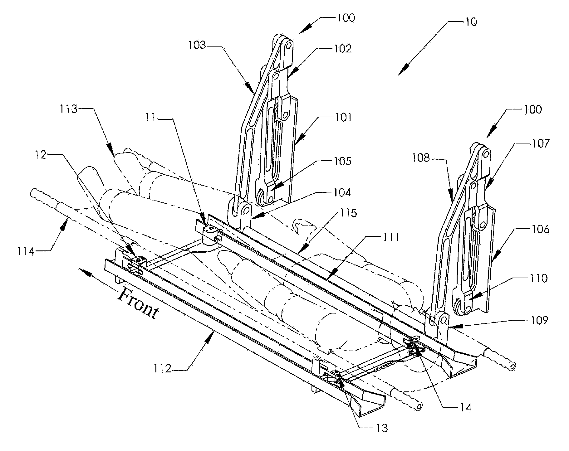
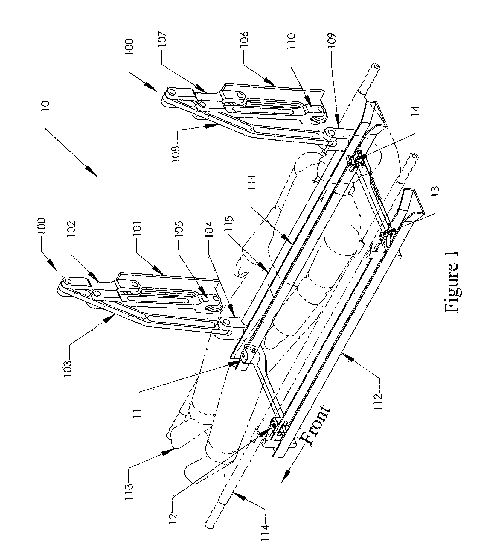
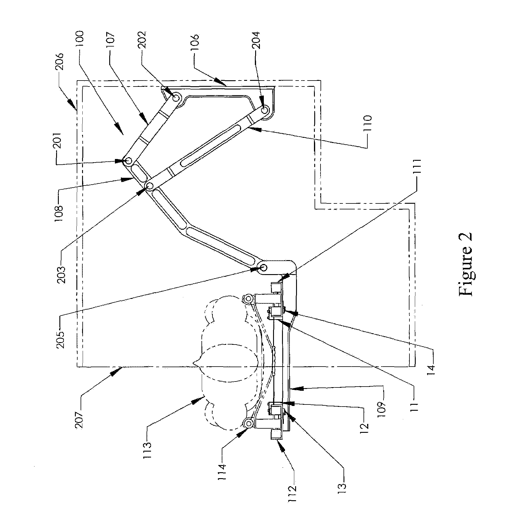
[0025]In a preferred embodiment of the patient support system of the present invention, a pair of litter support assemblies are attached to the opposing side walls in the cargo bed of a vehicle. For simplicity, only a single support assembly will be described. It will be clear to the artisan that a second assembly, adapted for attachment to an opposing side wall in the cargo bed, is a mirror image of the first assembly described below.

[0026]With reference to FIGS. 1 and 2, a litter support system 10 in accordance with the present invention comprises front 101 and rear 106 chassis mounting portions adapted to be attached to a side wall 206 (FIG. 2) in the bed of a vehicle (not shown), front and rear lateral adjustment portions 100 attached to the respective front and rear chassis mounting portions 1001 and 106 and a rectangular litter supporting portion comprising “C-channel” rails 111 and 112 attached to, and, in turn, supported by, members 104 and 109 of the lateral adjustment port...


PUM


Abstract

A patient support system adapted for attachment to the chassis of a vehicle. The vehicle has a cargo bed and a midline bisecting the cargo bed. The assembly includes a chassis mounting portion adapted to be attached to a side wall in the bed of the vehicle, a lateral adjustment mechanism attached to the chassis mounting portion and a litter supporting portion attached to the lateral adjustment mechanism. The assembly permits the litter supporting portion to be positioned near or over the midline of the cargo bed to facilitate the loading of a litter onto the litter supporting portion. After the litter lockingly engages the litter supporting portion, the litter supporting portion can be repositioned laterally with respect to the midline of the vehicle bed. In a preferred embodiment, two assemblies, each of which is a mirror image of the other, are attached to opposing walls in the cargo bed of the vehicle. When the assemblies are moved laterally, a corridor is created between adjacent litters that can be used by an attendant to provide life support.

Description

BACKGROUND OF THE INVENTION[0001]1. Field of the Invention[0002]The present invention relates to an assembly adapted for mounting in a vehicle, the assembly thereafter being operable for receiving, supporting and manipulating the position of a litter bearing a patient within the vehicle with minimal effort.[0003]2. Prior Art[0004]The medical transport systems currently used to load, handle, and unload patients in military and civilian ambulances involve considerable amounts of manual labor and time. Both the physical exertion of the medical attendants as well as the delay in treatment incurred while loading NATO style litters into a transport vehicle can have a negative affect on the patient. This is particularly significant in the case of ambulances that simultaneously transport several patients, where the physical effort and time associated with loading an occupied stretcher into the vehicle are multiplied by the number of patients to be transported.[0005]While performing certain ...

Claims


Application Information

Patent Timeline
Patent Type & Authority Patents(United States)
IPC IPC(8): A61G3/02
CPCA61G3/0254A61G3/0833A61G3/0841A61G3/0883A61G3/0891A61G3/085A61G1/06
Inventor MYERS, WILL J.FRIEDER, RUSSELLKUMARESAN, SRIRANGAMSANCES, JR., ANTHONY
Owner MYERS WILL J
Learn More