Exhaust emission control device

a technology of exhaust emission control and control device, which is applied in the direction of electrical control, machines/engines, separation processes, etc., can solve the problems of insufficient exhaust emission control effect and rare chance of temperature level of exhaust from diesel engines in normal operating status, and achieve good nox reduction effect, reduce electricity consumption, and reduce the effect of regenerated

Inactive Publication Date: 2008-02-19
HINO MOTORS LTD
View PDF13 Cites 21 Cited by
  • Summary
  • Abstract
  • Description
  • Claims
  • Application Information

AI Technical Summary

Benefits of technology

[0033]According to the above-mentioned exhaust emission control device of the invention, the following various excellent meritorious effects will be obtained:
[0034](I) According to an aspect of the invention, after the exhaust temperature may be increased as needs demand by temperature increasing means, fuel is added to the exhaust gas by the fuel adding means. The added fuel is oxidized through the oxidation catalyst and a resultant reaction heat substantially increases the temperature of the exhaust gas passing through the oxidation catalyst. This exhaust gas is introduced into the plasma generator to burn off the soot and SOF attached to and accumulated on the electrodes, so that preliminarily prevented is leakage of the current due to the soot and SOF attached to and accumulated on the electrodes, whereby proper voltage is applied with no hindrance across the electrodes to maintain well generation of plasma.
[0035](II) On the basis of the detected value of the temperature sensor, the fuel adding means and temperature increasing means can be properly operated to efficiently burn off the soot and SOF attached to the electrodes of the plasma generator.
[0036](III) Merely conducted is controlling the fuel injection unit so as to cause it to conduct post-injection following the main injection and with non-ignition timing later than a compressive top dead center, which make it possible to add unburned fuel to the exhaust gas with no need of new facilities annexed, thereby suppressing a runup of cost on fuel adding means.
[0037](IV) The working air quantity in the internal combustion engine is reduced to increase pumping loss; and exhaust gas to be generated in the combustion in the internal combustion engine is reduced to lower the heat capacity. As a result, the temperature of the exhaust gas to the oxidation catalyst can be surely increased.
[0038](V) Fuel of the delayed main injection is burned with timing hardly convertible into output, so that the heat efficiency of the internal combustion engine is lowered to increase heat quantity not utilized for motive energy among the heat release value of the fuel, whereby the temperature of the exhaust gas to the oxidation catalyst can be surely increased.

Problems solved by technology

However, the exhaust from the diesel engine in a normal operating status rarely has a chance to reach a temperature level at which the particulates ignite by themselves.
Thus, if an operating status with lower exhaust temperature (generally speaking, a region with lower exhaust temperature extends in a light-load operating region) continues, the post-processing device cannot work well and in a case of, for example, a city shuttle-bus which tends to travel on congested roads, operation above a predetermined temperature requirement does not continue for a long time, resulting in the possibility of insufficiently obtaining the exhaust emission control effect due to provision of a post-processing device.

Method used


Image

  • Exhaust emission control device
  • Exhaust emission control device
  • Exhaust emission control device

Examples


Embodiment Construction

[0042]Embodiments of the invention will be described with reference to the drawings.

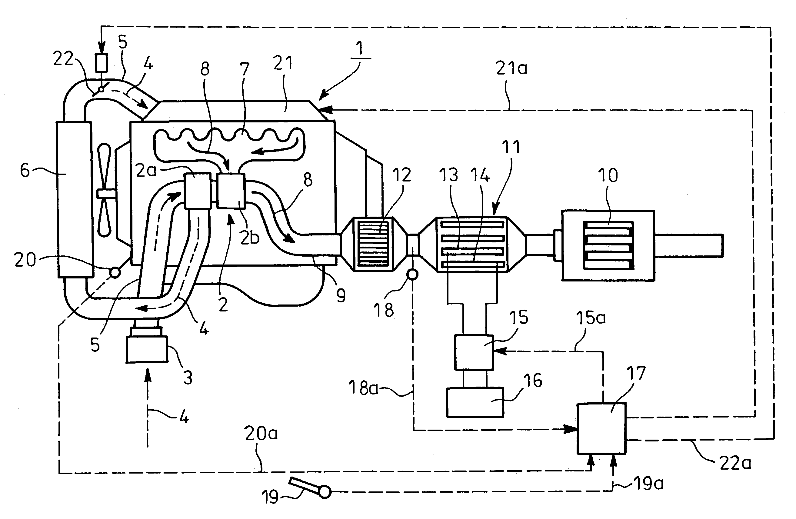
[0043]FIGS. 1 to 3 show an embodiment of the invention. In FIG. 1, reference numeral 1 designates a diesel engine (internal combustion engine) with a turbocharger 2. Suction air 4 sucked through an air cleaner 3 is guided via a suction pipe 5 to a compressor 2a of the turbocharger 2 so as to compress the same, the compressed suction air 4 being passed through an intercooler 6 and being distributed to respective cylinders of the diesel engine 1.

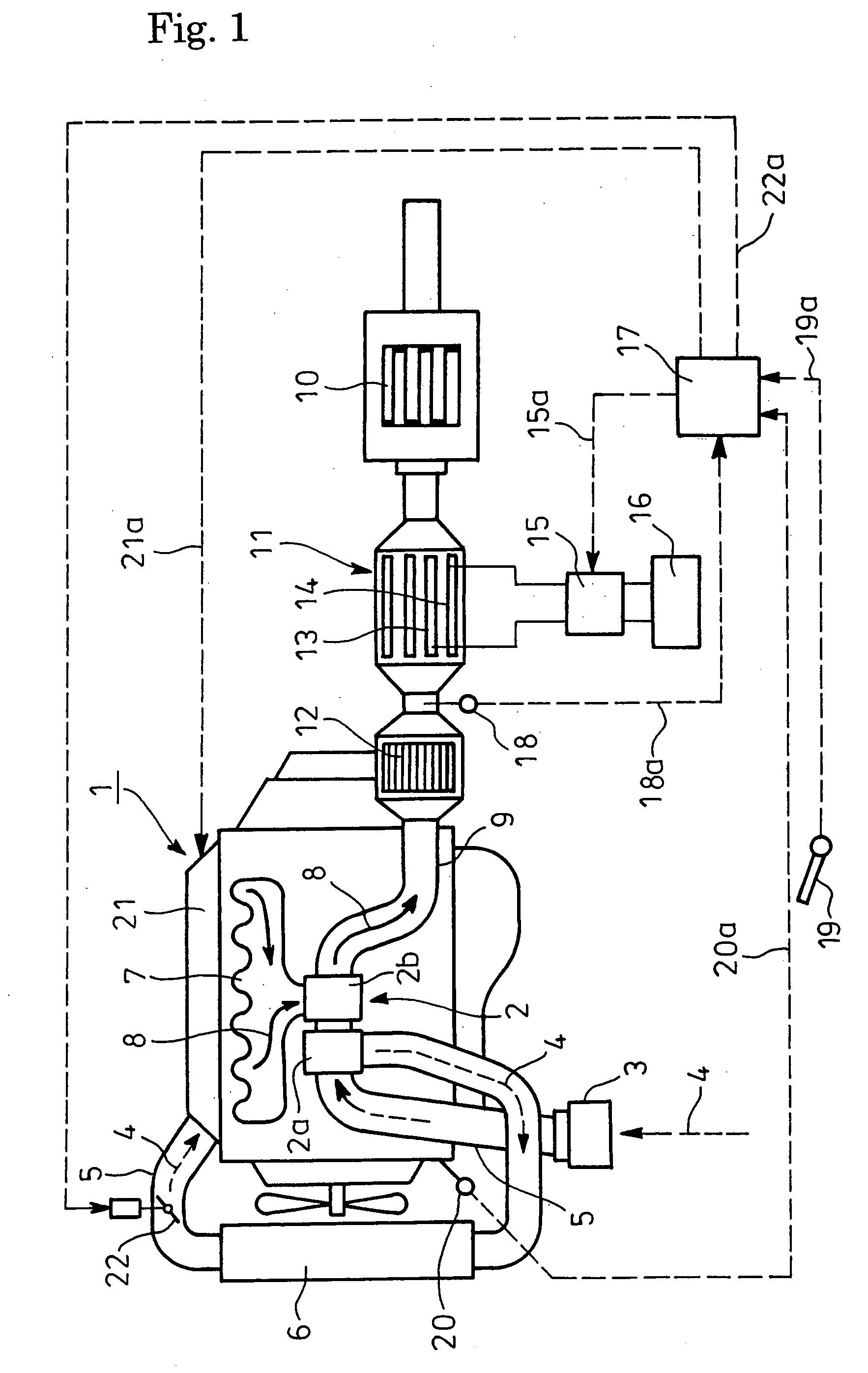
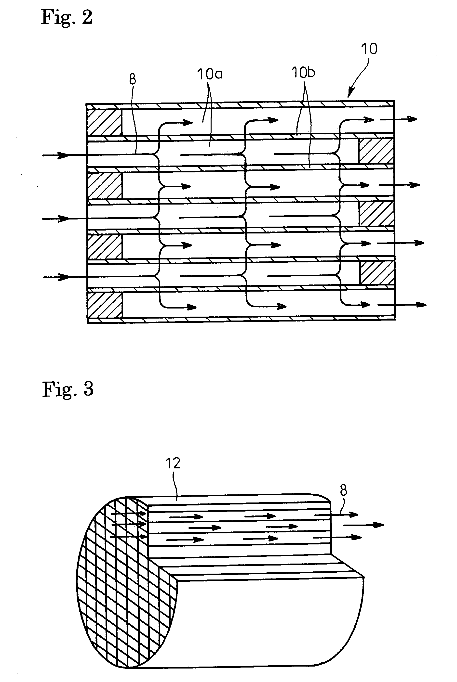
[0044]Exhaust gas 8 discharged via an exhaust manifold 7 from the respective cylinders of the diesel engine 1 is fed to a turbine 2b of the turbocharger 2; the exhaust gas 8 having driven the turbine 2b is passed through a catalyst regenerative particulate filter 10 (post-processing device) for capturing of particulates and is discharged.

[0045]As shown in FIG. 2 on an enlarged scale, the particulate filter 10 is a porous honeycomb structure made of ceramics hav...


PUM

PropertyMeasurementUnit
crank angleaaaaaaaaaa
exhaust temperatureaaaaaaaaaa

Abstract

Provided is an exhaust emission control device which can properly burn off soot and soluble organic fraction attached to and accumulated on electrodes of a plasma generator. The exhaust emission control device with a post-processing device (catalyst regenerative particulate filter) for allowing exhaust gas to pass therethrough for gas purification incorporated in an exhaust pipe of an internal combustion engine (diesel engine) comprises a plasma generator arranged upstream of the post-processing device for discharging electricity in the exhaust gas to generate plasma, flow-through type oxidation catalyst arranged upstream of the plasma generator, fuel adding means (controller) arranged upstream of the oxidation catalyst for adding fuel into the exhaust gas, temperature increasing means (suction throttling valve or controller) for increasing the exhaust temperature to a level enough for oxidation reaction on the oxidation catalyst of the fuel added by said fuel adding means.

Description

TECHNICAL FIELD[0001]The present invention relates to an exhaust emission control device.BACKGROUND ART[0002]Particulates or particulate matter emitted or discharged from a diesel engine is mainly constituted by carbonic soot and a soluble organic fraction (SOF) of high-boiling hydrocarbons, and contains a trace of sulfate (misty sulfuric acid fraction). In order to reduce emission of particulates from the engine, a particulate filter is conventionally employed and incorporated into an exhaust pipe through which the exhaust gas flows.[0003]This kind of particulate filter is a porous honeycomb structure made of ceramics such as cordierite and having lattice-like compartmentalized passages; alternate ones of the passages having plugged inlets and the remaining passages having unplugged open inlets which are plugged at their outlets. Thus, only the exhaust gas passing through the compartment walls is discharged downstream.[0004]The particulates in the exhaust gas, which are captured by...

Claims


Application Information

Patent Timeline
Patent Type & Authority Patents(United States)
IPC IPC(8): F01N3/00F01N3/033F01N3/035F01N3/08F01N3/28F01N13/02F02D41/02
CPCF01N3/033F01N3/035F01N3/0892F01N3/2882F01N13/009F02D41/0245F01N2570/04F02D41/029Y02T10/26F01N2240/28F01N3/103F01N2430/085F01N2560/06F01N2900/1404Y02T10/12B01D46/42B01D53/00B01D53/94F01N3/02
Inventor SHIMODA, MASATOSHI
Owner HINO MOTORS LTD
Why Eureka
Try Eureka