Metal shaping apparatus

a metal shaping and metal technology, applied in the field of metal shaping apparatus, can solve the problems of high price of presently available power hammers and formers, out of the reach of all but the largest metalworking operators, and achieve the effects of reducing costs, reducing costs, and reducing footprin

Inactive Publication Date: 2008-02-19
JSJ CORP
View PDF15 Cites 13 Cited by
  • Summary
  • Abstract
  • Description
  • Claims
  • Application Information

AI Technical Summary

Benefits of technology

[0006]The present disclosure addresses a power hammer assembly providing users with the metal forming advantages associated with power machinery at a reduced expense and in a smaller footprint than presently available power hammer systems. In general, the power hammer assembly of the present invention provides three-dimensional shaping capabilities, which have application in the forming of custom metal products such as, for example, customized motorcycle and automotive parts. The power hammer assembly of the present disclosure can be fabricated and assembled in a kit fashion with commonly available tools to reduce costs. Alternatively, the power hammer assembly of the present disclosure can be purchased in an assembled configuration.
[0007]In one aspect, a power hammer assembly of the present disclosure provides powered forming capabilities while remaining economical with respect to performance, vibration, footprint size and acquisition costs. In some embodiments, the power hammer assembly can comprise a power assembly for providing a single stroke speed and / or a single set stroke with respect to the striking of die assemblies against a piece of metal. In some embodiments, the power hammer assembly of the present invention can comprise a larger throat area and / or a larger die gap than presently available power hammers to facilitate ease of use. In some embodiments, the power hammer assembly of the present invention can comprise adjustment features allowing for the use of die sets of varying configurations such as, for example, shank size, shank length or alternatively, die sets fabricated for use with other machinery. In some embodiments, the power hammer assembly of the present invention can comprise a belt transmission assembly designed to slip in the event of die interference during set-up or operation so as to avoid damaging the power hammer assembly. In some embodiments the power hammer assembly of the present invention includes fine adjustment means for spacing between the upper and lower die.

Problems solved by technology

Unfortunately, using presently available power hammers and formers can subject users to a number of inherent disadvantages.
Generally, presently available power hammers and formers are expensive and may cost on the order of tens of thousands of dollars putting them out of reach of all but the largest metalworking operators.
Presently, available power hammers and formers tend to be bulky and occupy large footprints making them unsuitable for small-scale operations.
In addition, presently available power hammers and formers can require precise, custom machined die sets, which may be unusable with other machinery, in order to provide proper operational clearance.

Method used


Image

  • Metal shaping apparatus
  • Metal shaping apparatus
  • Metal shaping apparatus

Examples


Embodiment Construction

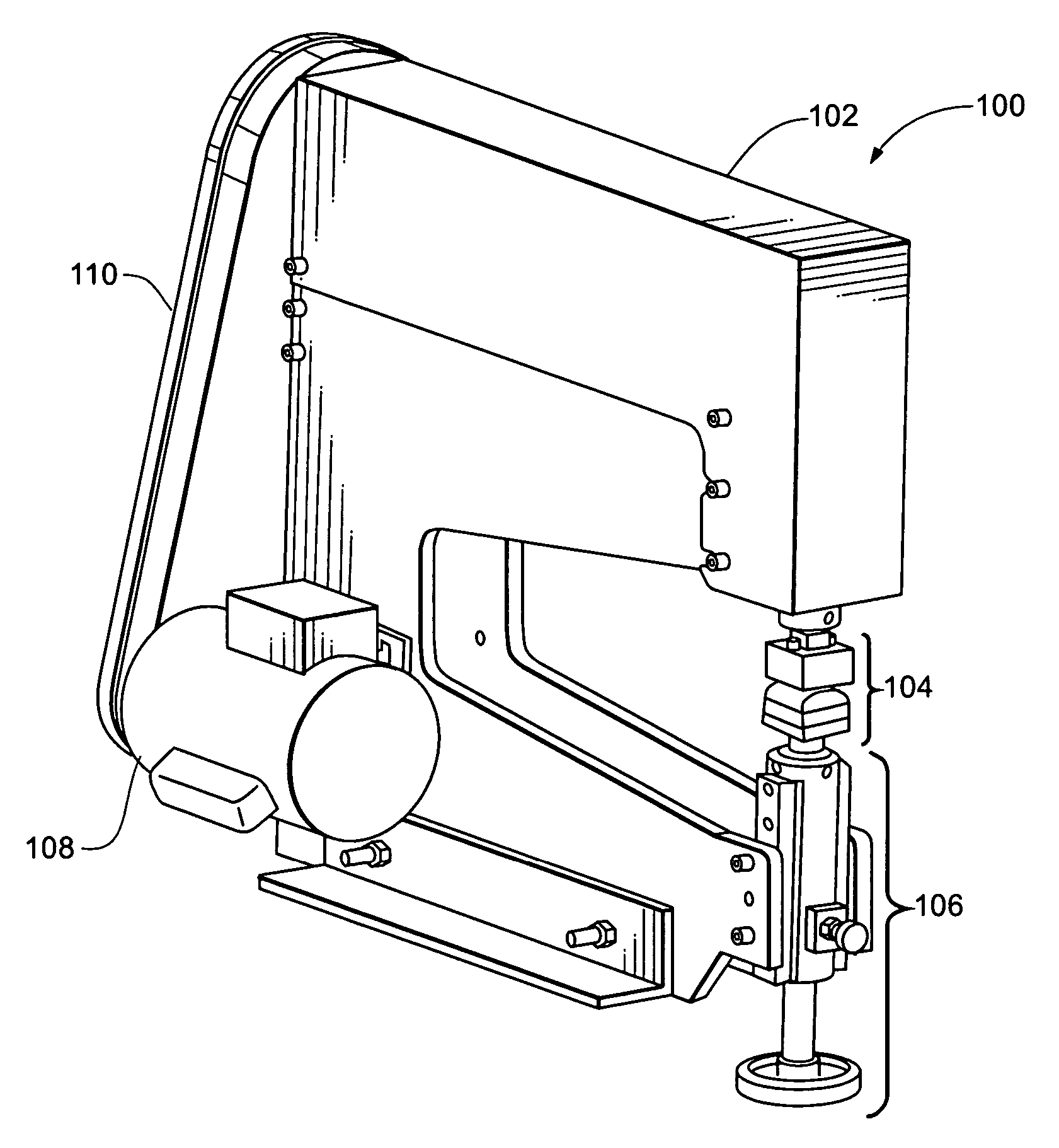
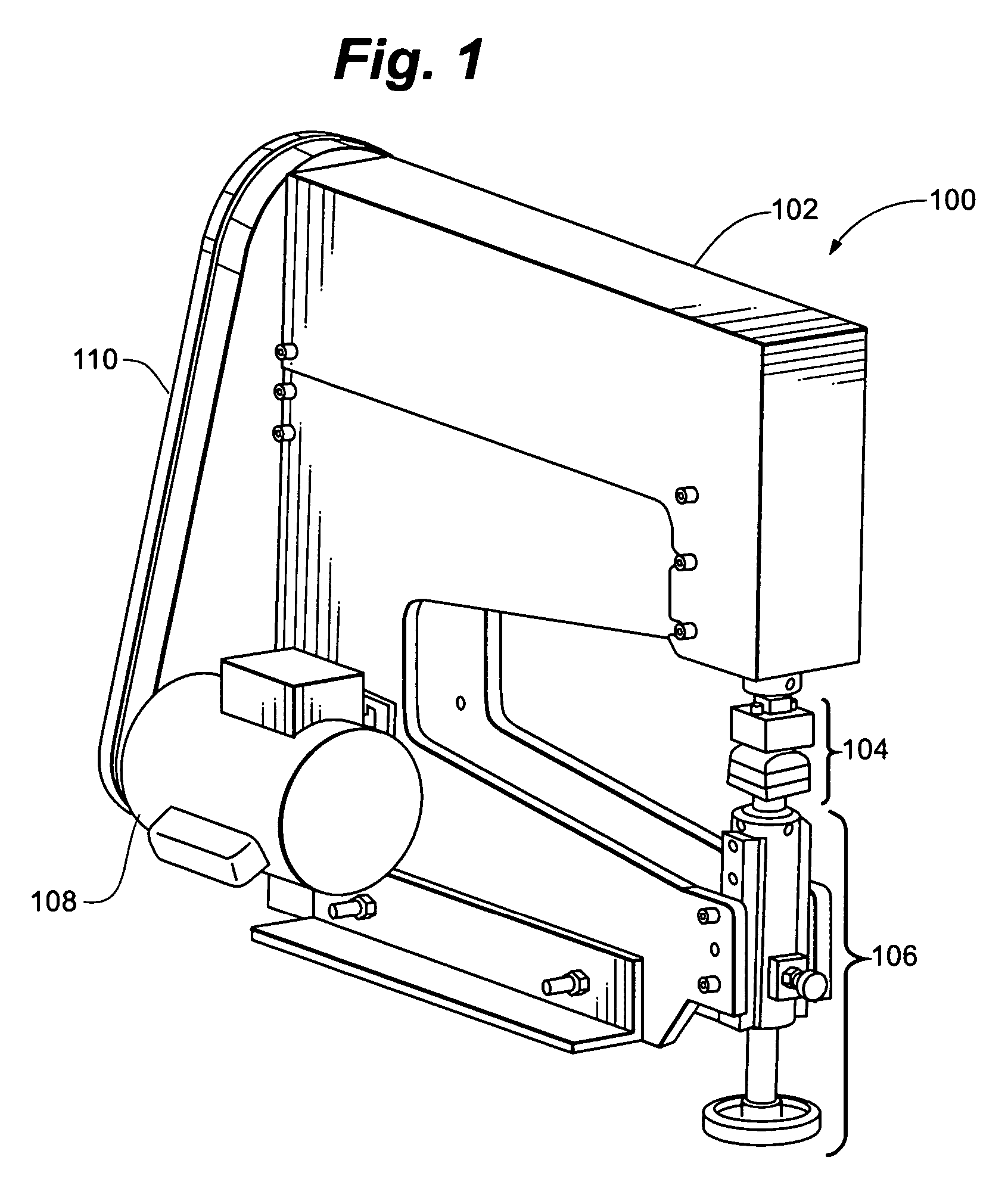
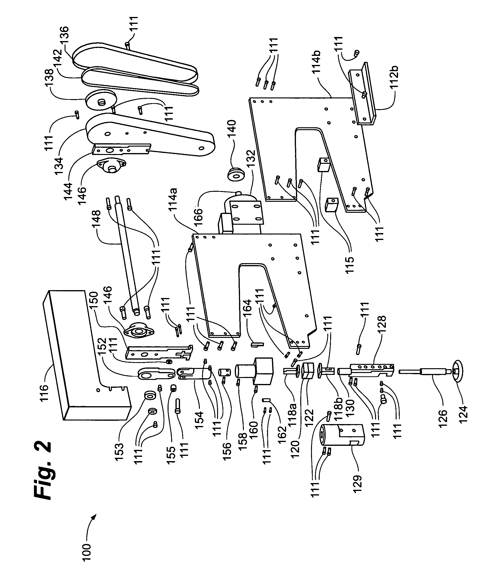
[0025]As illustrated in FIGS. 1, 2, 3, 4, 5, 6, 7, 10 and 10a, a power hammer assembly 100 of the present invention provides the ability to shape metal with a reduced footprint, vibration-free power tool. With reference to FIG. 1, power hammer assembly 100 generally comprises a body assembly 102, a forming die portion 104, a die adjustment portion 106, a motor portion 108 and a belt transmission portion 110. Power hammer assembly 100 can be fabricated so as allow assembly with the use of suitable fasteners 111 such as, for example, screws.

[0026]As shown in detail in FIGS. 2 and 3, body assembly 102 comprises a pair of support base assemblies 112a, 112b, a pair of side plates 114a, 114b, a pair of base spacers 115 and a shroud cover 116. Forming die portion 104 comprises a pair of die holders 118a, 118b, a female shrinking die 120 and a male shrinking die 122. Female shrinking die 120 and male shrinking die 122 can comprise machined, hand polished hardened steels such as, for example...


PUM

PropertyMeasurementUnit
depthaaaaaaaaaa
lengthaaaaaaaaaa
stroke speedaaaaaaaaaa

Abstract

A power hammer assembly providing forming capabilities while remaining economical with respect to performance, vibration, footprint size and acquisition costs. The power hammer assembly can provide for a single stroke speed and / or a single set stroke with respect to the striking of die assemblies against a piece of metal. The power hammer assembly can provide for a large throat area and / or a larger die gap for ease of use. The power hammer assembly can include adjustment features allowing for the use of die sets of varying configurations such as, for example, shank size, shank length or alternatively, die sets fabricated for use with other machinery. In addition, the power hammer assembly can include a belt transmission assembly designed to slip in the event of die interference during set-up or operation so as to avoid damaging the power hammer assembly.

Description

PRIORITY CLAIM[0001]The present application claims priority to U.S. Provisional Application No. 60 / 660,782, filed Mar. 11, 2005, and entitled, “METAL SHAPING APPARATUS,” which is herein incorporated by reference in its entirety.FIELD OF THE INVENTION[0002]The invention relates generally to the field of shaping metal. More particularly, the present invention pertains to a power hammer assembly capable of economically providing three-dimensional shaping capabilities.BACKGROUND OF THE INVENTION[0003]A variety of methods and machines are presently available for shaping metal into three-dimensional parts. Recently, the popularity of such metal shaping methods and machines has been increased due to the number of television programs dealing with custom metal shaping in the context of motorcycle and automobile customization. As such, a new generation of potential customizers and users has been introduced to the art and skill of metalworking.[0004]Prior to the development of power machinery,...

Claims


Application Information

Patent Timeline
Patent Type & Authority Patents(United States)
IPC IPC(8): B21J13/00
CPCB21J7/04B21J13/02
Inventor BORGWARTH, DENNIS
Owner JSJ CORP
Why Eureka
Try Eureka