Premium threaded tubular joint comprising at least a threaded element with end lip

a tubular connection and end lip technology, applied in the direction of screw threaded joints, hose connections, mechanical equipment, etc., can solve the problems of reducing the service life of the tubular connection. , to achieve the effect of reducing the axial stiffness of the lip, and increasing the elastic deformation

Inactive Publication Date: 2008-02-26
NIPPON STEEL CORP
View PDF18 Cites 64 Cited by
  • Summary
  • Abstract
  • Description
  • Claims
  • Application Information

AI Technical Summary

Benefits of technology

[0044]Such an effect cannot be known or deduced from the Tung patent, which does not consider such distal axial abutment surfaces.
[0045]The inventors have also noted a further non obvious effect of the appendix on the threaded tubular connection of the invention.
[0046]The appendix reduces the axial stiffness of the lip and as a result, increases the elastic deformation of the lip at constant axial compressive stress.
[0047]When a tensile load is exerted on the threaded connection, this increased elastic deformation can shift the detachment of the abutment and especially the critical value of the integrated contact pressure over the width of the lip sealing surface towards relatively high tensile loads.
[0048]Here again, such an effect could not be discovered or deduced in an obvious manner from the Tung patent, which does not consider threaded tubular connections provided with a distal abutting sealing surface and which does not consider the risks of leakage under tensile stresses.

Problems solved by technology

The interfering sealing surfaces can cause problems with galling during make up if they have an unsuitable geometry.
They can also run the risk of leaking in service if the contact pressure, and in particular the integrated contact pressure over the active width of the sealing surfaces, is insufficient.
It is particularly difficult to obtain a threaded tubular connection that resists, in a manner equivalent to a pipe, the different stresses in service and which remains gas tight under such stresses, the stress after makeup being modified by the application of external stresses in service, for example axial tension or compression, bending, internal or external pressure.

Method used


Image

  • Premium threaded tubular joint comprising at least a threaded element with end lip
  • Premium threaded tubular joint comprising at least a threaded element with end lip
  • Premium threaded tubular joint comprising at least a threaded element with end lip

Examples


Embodiment Construction

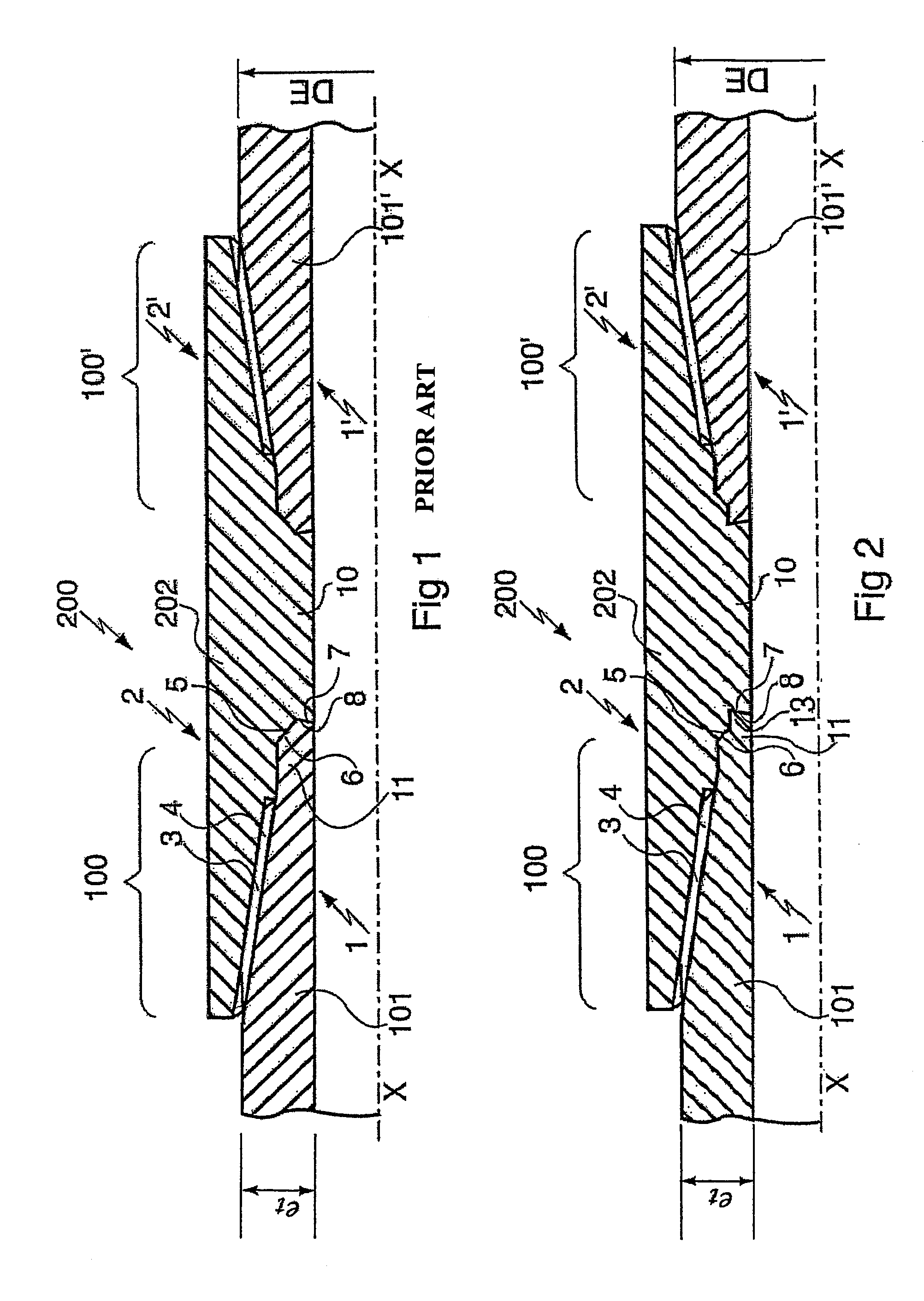
[0073]FIG. 1 shows a prior art threaded and coupled tubular connection 200 between two pipes 101, 101′, which are great-length pipes, via a coupling 202 which is a short-length tubular component.

[0074]The term “pipe” or “great-length tubular component” means pipes several meters long, for example about 10 m long.

[0075]Connections 200 are routinely used to produce casing or tubing strings for hydrocarbon wells, risers or for drillpipe strings for said wells.

[0076]The pipes can be produced from any type of non alloyed, light alloy or heavy alloy steel or even from heat treated or cold-worked ferrous or non ferrous alloys depending on the service conditions such as: mechanical stress level, corrosive nature of the fluid internal to or externally of the pipes.

[0077]It is also possible to use steel tubes with low corrosion resistance provided with a coating, for example of synthetic material preventing any contact between the steel and the corrosive fluid.

[0078]The ends of pipes 101, 101...


PUM


Abstract

A premium threaded tubular connection including, on at least one threaded element, a distal abutment surface at the free end of a threaded element, and a lip sealing surface at a given distance from the threading. The lip includes an appendix that extends the lip towards its free end beyond the lip sealing surface so that the lip has both high radial stiffness and low axial stiffness. This results in enhanced performance as regards the seal of the threaded connection under pressure and/or under tension, and other advantages of precision of real makeup torque, mechanical strength in axial compression, a shock barrier effect, and tolerance in engaging the threaded elements.

Description

BACKGROUND OF THE INVENTION[0001]1. Field of the Invention[0002]The invention relates to premium threaded tubular connections comprising at least one set of metal-metal sealing surfaces and makeup abutments on male and female elements that make up the threaded connection, the threaded elements being formed at the end of a tubular component of a great-length pipe or short (coupling) type.[0003]2. Description of the Related Art[0004]Many types of threaded tubular connections are known, primarily used to constitute casing strings or tubing strings or drillpipe strings for hydrocarbon or the like wells, such as geothermal wells.[0005]Threaded tubular connections are also known on riser columns for connecting sea bottom wells to offshore production platforms.[0006]Such threaded tubular connections are subjected to a variety of overall stresses (axial tension or compression, internal or external fluid pressure, bending, torsion), which may be combined (for example axial tension+internal p...

Claims


Application Information

Patent Timeline
Patent Type & Authority Patents(United States)
IPC IPC(8): F16L25/00E21B17/042F16L15/00F16L15/04F16L15/06
CPCE21B17/042F16L15/00F16L15/004F16L15/06
Inventor DUTILLEUL, PIERREROUSSIE, GABRIEL
Owner NIPPON STEEL CORP
Why Eureka
Try Eureka