Rearview mirror assembly construction

a rearview mirror and assembly technology, applied in the direction of printed circuit non-printed electric components, printed circuit boards, instruments, etc., can solve the problems of difficult mounting of leds at the appropriate angle, affecting the performance of turn indicators, and leds being prone to bending and breaking, so as to increase the adhesiveness of the encapsulating material

Inactive Publication Date: 2008-02-26
GENTEX CORP
View PDF103 Cites 63 Cited by
  • Summary
  • Abstract
  • Description
  • Claims
  • Application Information

AI Technical Summary

Benefits of technology

[0022]According to another embodiment, a rearview mirror assembly for a vehicle comprises: a mirror having a surface that is at least partially reflective; a flexible circuit board disposed behind the surface of the mirror and having a first surface and second surface opposite the first surface; an LED chip mounted to the first surface of the flexible circuit board and electrically coupled to conductive tracings provided on the flexible circuit board; and an encapsulant molded over and around the LED chip. The surface of the encapsulant may form a lens to direct the light output of the LED chip at the desired angle. There may or may not be rigid circuit board attached to the flexible circuit board in the area of the LED die to prevent the die from becoming dislodged. The rigid circuit board may consist of holes that line up with holes in the flexible circuit board to permit the encapsulant material to flow into these holes to increase the adhesiveness of the encapsulating material.
[0023]According to another embodiment, a rearview mirror assembly for a vehicle comprises: an electrochromic mirror having front and rear surfaces and first and second electrical connectors disposed along edges of the electrochromic mirror; and a flexible circuit board disposed behind the rear surface of the electrochromic mirror and having a first surface facing the rear surface of the electrochromic mirror and a second surface opposite the first surface, wherein the flexible circuit board includes printed electrical circuits that are terminated with connectors that provide an electrical connection with the electrical connectors of the electrochromic mirror, the printed electrical circuits extending to a common location on the flexible circuit board to provide mirror control terminals for connection to a source of a mirror control signal.
[0024]According to another embodiment, a rearview mirror assembly for a vehicle comprises: a mirror having front and rear surfaces; a flexible circuit board disposed behind the rear surface of the mirror and having a first surface facing the rear surface of the mirror and a second surface opposite the first surface; and a turn indicator having at least one light source. The flexible circuit board includes a resistive conductor extending back and forth across the first surface of the flexible circuit board to function as a mirror heater. The resistive conductor begins and ends at a common location on the flexible circuit board to provide heater power terminals for connection to a source of heater power. The flexible circuit board includes conductive paths extending therethrough from a location proximate the light source to the common location to provide turn indicator control terminals proximate the heater power terminals for connection to a source of a turn indicator control signal.

Problems solved by technology

Mounting LEDs at the appropriate angle is difficult using conventional electronic component placement equipment.
One problem with this approach is that two of the leads of each LED 54 are not secured firmly to circuit board 50, and the LEDs are thus prone to bending and breaking in which case performance of the turn indicator is compromised.
In general, the sealant is not very effective for holding the two unsecured leads of each LED to that surface of the circuit board.
Additionally, the sealant may act as a thermal insulator and not allow for sufficient dissipation of heat generated by the circuit components and the LEDs.
Because the brightness of the LEDs is a direct function of the current that may be passed through the LEDs, the use of a sealant in this manner may significantly reduce the brightness of the LEDs.
Another problem associated with placing LEDs, particularly those mounted at an angle, to a circuit board behind a mirror and a rearview mirror assembly is the lack of space available for such a configuration.
Consequently, there is not a significant volume available within the mirror housing for additional components to be placed.
For these reasons, designers are presented with a significant challenge when attempting to design a signal mirror.
Another problem associated with placing a light module behind a mirror is properly aligning the light sources with the window regions in the mirror.
Another problem associated with providing a multitude of components such as those shown in FIG. 2 within a rearview mirror housing is the resultant difficulty in assembling the mirror housing and attaching it to the vehicle and making the necessary electrical connections.
Such plugs take time to ensure proper connection with the associated receptacle, increase the number of parts, and consume additional volume within the limited space of the rearview mirror housing.
Such wires add to the cost of the system since they must be appropriately stripped and appropriate soldering, operations, and electrical connections must be made in addition to the fact that such operations introduce possible defects along with breaks in the wiring.
Reversal of the polarity of these connections may result in damage to the electrochromic mirror.
Thus, the wiring utilized to connect the electrochromic mirror to the appropriate mirror control circuit could readily be connected in the wrong positions within a plug receptacle thereby accidentally causing damage to the electrochromic mirror.
Thus, the use of a third surface electrochromic mirror may further add to the difficulties in providing proper electrical connections to all the components disposed within a rearview mirror housing.

Method used


Image

  • Rearview mirror assembly construction
  • Rearview mirror assembly construction
  • Rearview mirror assembly construction

Examples


third embodiment

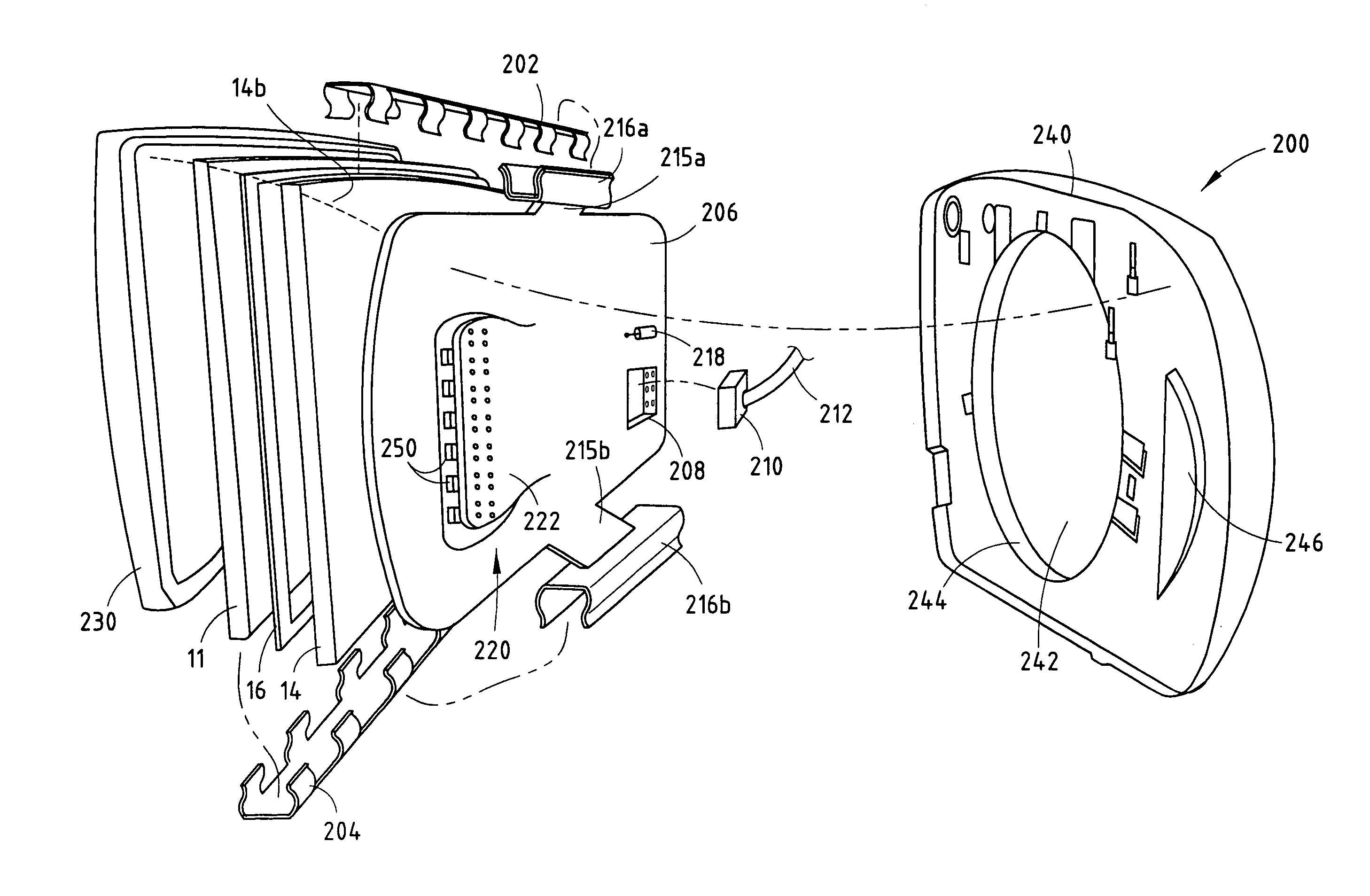
[0064]The printed circuit board 206 of the third embodiment preferably includes a pair of conductive tracings 236a and 236b, which extend from locations approximate the corresponding pins of connector plug 208 to conductive clips 216a and 216b, respectively. Further, a pair of conductive tracings 238 may extend from the location underlying plug 208 to the plurality of LEDs 250 mounted on the forward surface of circuit board 206. Current limiting resistors (not shown) to be coupled to LEDs 250 can be either surface mount components or carbon ink resistors. The die of a reverse protection diode could also be placed onto the copper circuitry to protect from backpowering the wire harness from LEDs 250 from improper electrical connection.

[0065]FIG. 12 shows an alternative technique for forming an LED 250 directly on the forward-facing surface of a flexible printed circuit board 206. As shown, LED 250 includes an LED chip 252, which again is surface mounted directly on the forward-facing ...

fourth embodiment

[0067]FIG. 13 shows a cross-sectional view of the present invention whereby an LED device 250 is mounted to the rear surface of a circuit board 206, which again is preferably a flexible circuit board. To allow light to pass through circuit board 206, an aperture or other transparent region 270 is provided in circuit board 206 in the area in front of LED 250. This substantially transparent region or window 270 may have a diffusant dispersed integrally therein or may have a roughened surface so as to diffuse the light from the LED device 250. An aperture 248 may be formed in carrier plate 240 to accommodate the height of LED 250 extending rearwardly behind the rear surface of printed circuit board 206. In the embodiment shown in FIG. 13, an optical deviator film 272 is provided over the transparent region 270 of circuit board 206 and in front of LED 250. In this manner, LED 250 may be mounted with its optical axis normal to the printed circuit board 206 with the optical deviator film ...


PUM


Abstract

A rearview mirror assembly of the present invention includes a circuit board disposed behind the mirror. The circuit board may be a flexible circuit board and may include an LED mounted to project light through a transparent window in the flexible circuit board and through the mirror. The flexible circuit board may function as a mirror heater and may include conductive paths for connection to the LED and/or electrodes of an electrochromic mirror. The LED may include an LED chip mounted directly on the circuit board and encapsulated thereon by an encapsulant.

Description

CROSS-REFERENCE TO RELATED APPLICATIONS[0001]This application is a continuation of U.S. patent application Ser. No. 10 / 105,574 filed on Mar. 25, 2002, now U.S. Pat. No. 6,657,767, issued on Dec. 2, 2003, which is a continuation-in-part of U.S. patent application Ser. No. 09 / 862,414 filed on May 21, 2001, now U.S. Pat. No. 6,650,457, issued on Nov. 18, 2003 filed on May 21, 2001, the entire disclosures of which are incorporated herein by reference.BACKGROUND OF THE INVENTION[0002]The present invention generally relates to a rearview mirror assembly for a vehicle. More particularly, the present invention relates to a rearview mirror assembly having a turn indicator incorporated therein and / or a flexible circuit board. The invention also pertains to subassemblies for use in a rearview mirror assembly in which an LED is mounted to a circuit board in a novel manner.[0003]Outside rearview mirror assemblies incorporating turn signal indicators have become increasingly popular. An example o...

Claims


Application Information

Patent Timeline
Patent Type & Authority Patents(United States)
IPC IPC(8): B60Q1/26B60R1/12B60R1/07B60R1/08H05K1/02H05K1/18H05K3/00
CPCB60Q1/2665B60R1/07B60R1/088B60R1/1207H05K1/18H05K1/189H05K1/02H05K3/0058H05K2201/09072H05K2201/09081H05K2201/10106H05K2201/10484
Inventor BONARDI, TIMOTHY A.BEUTE, RANDALL J.BRAUN, RANDALL S.
Owner GENTEX CORP
Why Eureka
Try Eureka