Split ring retainer for turbine outer air seal

a technology of turbine rotor blade and retainer, which is applied in the direction of machines/engines, stators, liquid fuel engines, etc., can solve the problems of extending the aircraft down time, reducing the service life of the air seal retention system, and reducing the number of premature failures. , the effect of reducing the weight and the cost of the turbine stag

Active Publication Date: 2008-02-26
RTX CORP
View PDF2 Cites 21 Cited by
  • Summary
  • Abstract
  • Description
  • Claims
  • Application Information

AI Technical Summary

Benefits of technology

[0006]A further object of the present invention is to reduce the number of premature failures in jet engine turbine air seal retention systems.
[0007]A still further object of the present invention is to reduce the amount of time needed to install and remove a turbine stage outer air seal retainer of a jet engine.
[0008]Another object of the present invention is to reduce the weight and the cost of a turbine stage outer seal retainer.
[0009]Another object of the present invention is to provide for a more rapid aircraft turn around time during periods of engine maintenance.
[0010]Yet another object of the present invention is to provide a turbine outer air seal retainer that can be installed or removed without the need of special tools.
[0011]These and other objects of the present invention are attained by a split ring retainer that prevents axial displacement of an annular series of locking key segments which serve to hold the outer air seal assembly of a jet engine turbine rotor stage in locking engagement with the turbine casing. The body of the split ring is slidably contained within a radially disposed groove in the turbine casing and has a series of circumferentially spaced raised lugs located around the inside surface of the ring body. The inner surfaces of the lugs approximate a circle having a first diameter and are adapted to seat upon axially extended ribs located upon each of the key segments. The ribs have seats for receiving the lugs thereon. The seats approximate a circle having a second diameter that is greater than the diameter described by the inner surfaces of the ribs so that the split ring is flexed outwardly when the lugs are seated upon the ribs. When seated upon the ribs, the ring engages each of the key segments to prevent axial movement of the segments and thus retain the segments in a locking position with the outer air seal assembly.

Problems solved by technology

Heretofore, the installation and removal of this type of retainer has been relatively difficult and time consuming when engine maintenance was required, thus extending the aircraft down time.
In addition, the air seal retention systems that are in present day use are relatively heavy and costly devices requiring the use of special tools to install or remove from the engine.
As a result, thermal loads developed during engine operation can produce further compressive loading upon the retainer causing the retainer to move, which can lead to premature failure of the retention system.

Method used


Image

  • Split ring retainer for turbine outer air seal
  • Split ring retainer for turbine outer air seal
  • Split ring retainer for turbine outer air seal

Examples


Embodiment Construction

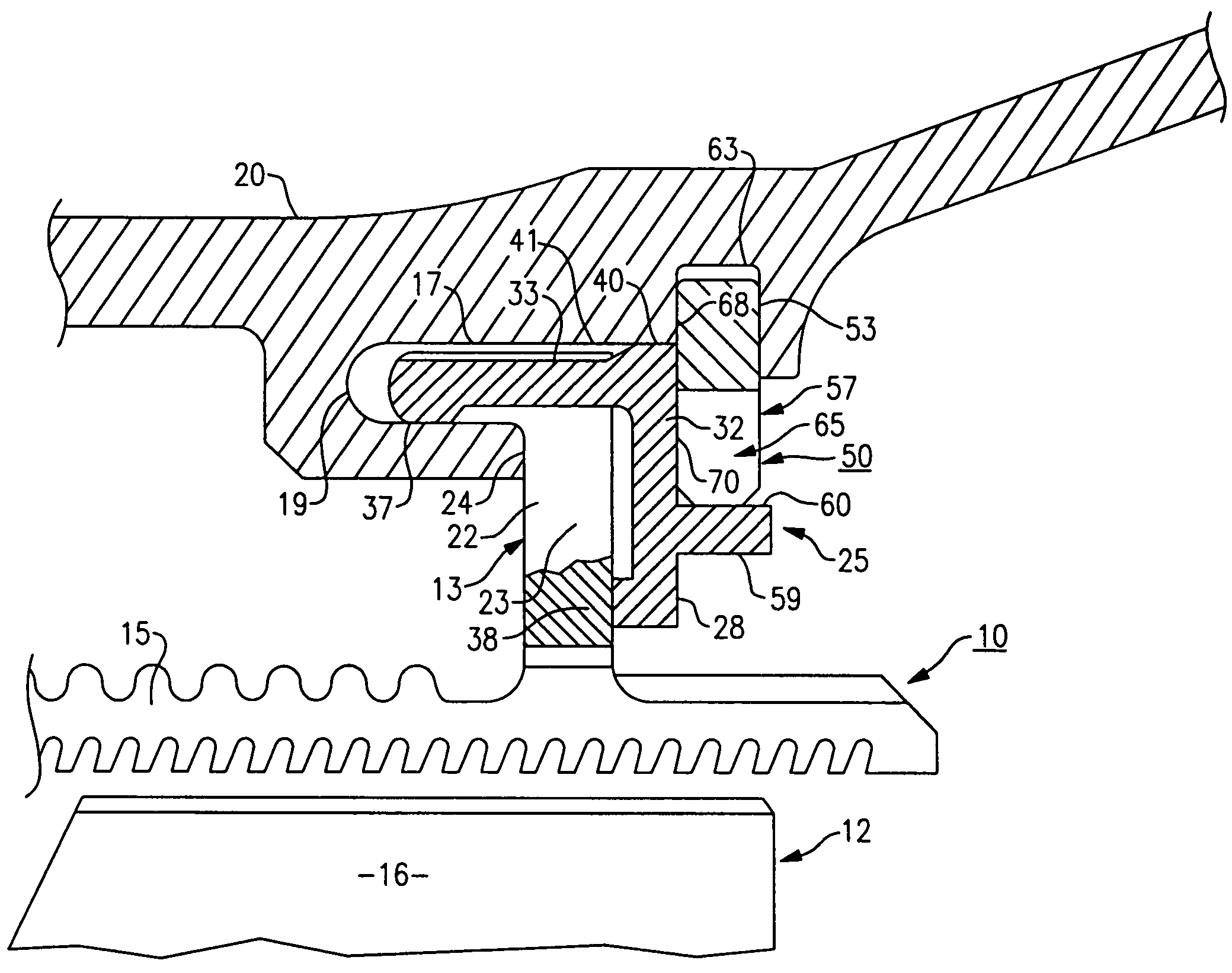
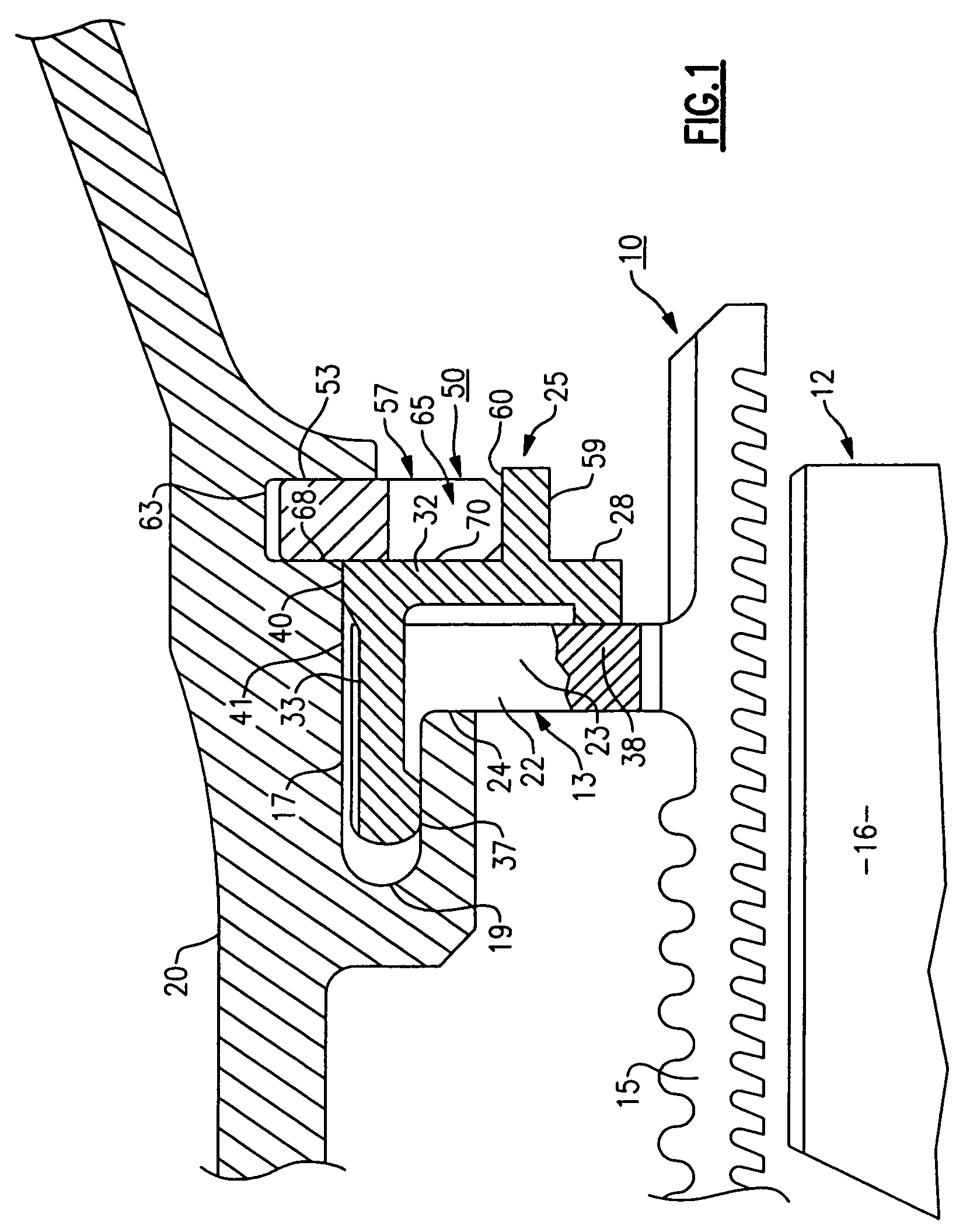
[0024]Referring initially to the drawings, there is illustrated a partial side elevation in section in FIG. 1 showing an annular outer air seal assembly 10 of a turbine rotor stage 12. The seal assembly contains a circular hook-shaped hanger 13 for locating the air seal 15 around the top edges of the blades 16 of the rotor stage. The hanger contains an annular flange 17 that is received within an axially disposed annular groove 19 formed in the turbine casing 20.

[0025]The air seal is connected to the annular flange 17 by means of a radially disposed arm 22. One side wall 23 of the arm bears against a radially disposed surface 24 located on the casing to register the air seal in assembly. A locking mechanism, generally referenced 25, serves to secure the air seal in a locked and registered position as illustrated in FIG. 1. The locking mechanism includes a plurality of arcuate-shaped key segments 28. Each key segment includes a radially disposed arcuate-shaped panel 32 having one or ...


PUM


Abstract

A retainer for securing the outer air seal assembly of a turbine rotor stage in a locked position. The outer air seal is suspended from the turbine casing over the rotor stage and is locked to the casing by annular segmented locking keys. A series of circumferentially spaced seats are located upon the front face of the locking key segments with the outer surfaces of the seats describing a circle approximating a first diameter. A split ring retainer is slidably carried in a radially disposed groove and is arranged to secure the key segments in a locked position. A series of lugs extend inwardly from the inside wall of the ring. The lugs are circumferentially spaced about the ring with the inner surface of the lugs approximating a circle having a second diameter that is less that of the first diameter approximated by the seats. The lugs are spaced so that each lug can be seated upon a seat to flex the ring outwardly in a radial direction and thus secure the key segment in a locking position.

Description

STATEMENT OF GOVERNMENT INTEREST[0001]The United States Government has certain rights in this invention pursuant to Contract No. N00019-02-C-3003 between the United States Navy and United Technologies Corporation.FIELD OF THE INVENTION[0002]This invention relates to a method and apparatus for retaining the outer air seal of a turbine rotor blade stage in assembly.BACKGROUND OF THE INVENTION[0003]More specifically, this invention pertains to an improved means for retaining the outer air seal of a jet engine turbine rotor stage in assembly. Heretofore, the installation and removal of this type of retainer has been relatively difficult and time consuming when engine maintenance was required, thus extending the aircraft down time. In addition, the air seal retention systems that are in present day use are relatively heavy and costly devices requiring the use of special tools to install or remove from the engine.[0004]Many air seal retainers used in jet engines are loaded in assembly inw...

Claims


Application Information

Patent Timeline
Patent Type & Authority Patents(United States)
IPC IPC(8): F01D11/02
CPCF01D9/04F01D11/08F01D25/246Y02T50/671Y02T50/60
Inventor TRINKS, STEVEN W.LEMIEUX, STEVEN G.REINHARDT, GREGORY E.
Owner RTX CORP
Why Eureka
Try Eureka