Switching power converter that supports both a boost mode of operation and a buck mode of operation using a common duty-cycle timing signal

a technology of switching power converters and duty-cycle timing signals, applied in the direction of dc-dc conversion, power conversion systems, climate sustainability, etc., can solve the problems of inefficiency, noisy behavior, unfavorable smooth transition between boosting and bucking, etc., to reduce ripple, switching transients, and eliminate overlap

Active Publication Date: 2008-02-26
QORVO US INC
View PDF10 Cites 186 Cited by
  • Summary
  • Abstract
  • Description
  • Claims
  • Application Information

AI Technical Summary

Benefits of technology

[0005]The present invention is a switching power converter that supports both a boost mode of operation and a buck mode of operation, uses one energy storage element, transitions smoothly between boosting and bucking, and avoids simultaneous boosting and bucking. The switching power converter uses a common duty-cycle timing signal and a common duty-cycle setpoint signal to provide a smooth transition between boosting and bucking, and to eliminate overlap between boosting and bucking. A voltage input error integrator is used to integrate out errors between an output voltage and a setpoint voltage to provide the common duty-cycle setpoint signal. Duty-cycle error integrators are used to integrate out errors between the common duty-cycle setpoint signal and the actual duty-cycle of either the buck converter or the boost converter. No...

Problems solved by technology

Existing designs may use separate timing and control circuitry for buck circuitry and boost circuitry; therefore, one problem facing such a switching power converter is operating when the input voltage is nearly equal to the output v...

Method used


Image

  • Switching power converter that supports both a boost mode of operation and a buck mode of operation using a common duty-cycle timing signal
  • Switching power converter that supports both a boost mode of operation and a buck mode of operation using a common duty-cycle timing signal
  • Switching power converter that supports both a boost mode of operation and a buck mode of operation using a common duty-cycle timing signal

Examples


Embodiment Construction

[0022]The embodiments set forth below represent the necessary information to enable those skilled in the art to practice the invention and illustrate the best mode of practicing the invention. Upon reading the following description in light of the accompanying drawing figures, those skilled in the art will understand the concepts of the invention and will recognize applications of these concepts not particularly addressed herein. It should be understood that these concepts and applications fall within the scope of the disclosure and the accompanying claims.

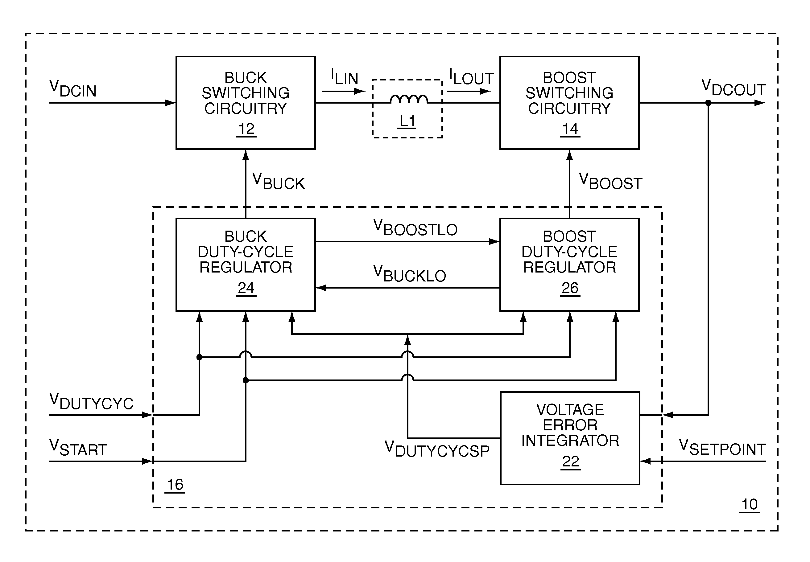
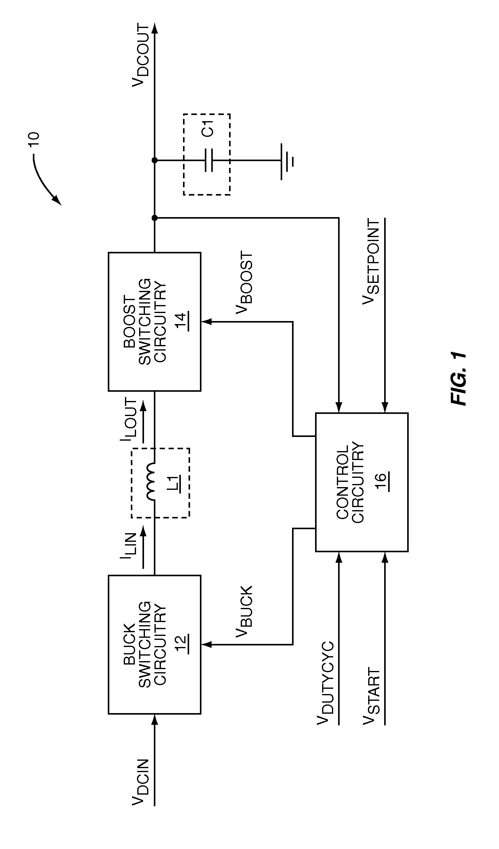
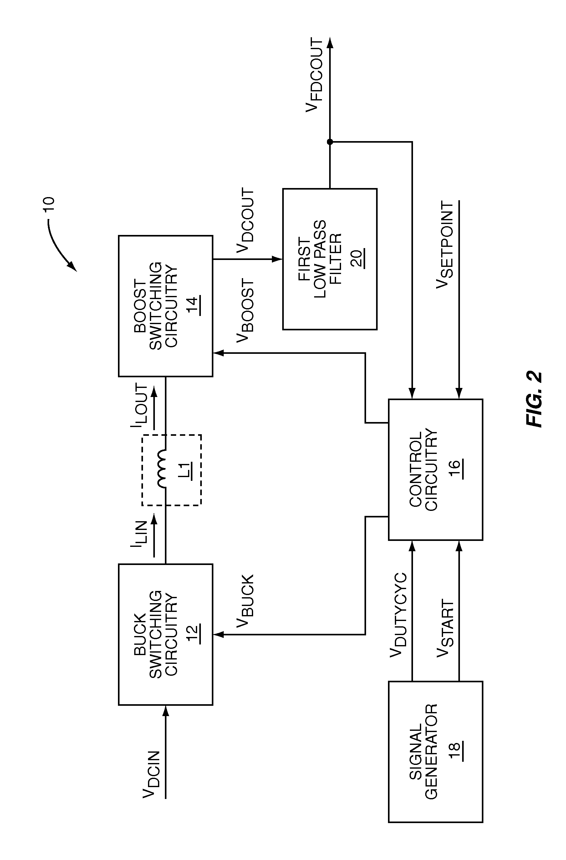
[0023]The present invention is a switching power converter that supports both a boost mode of operation and a buck mode of operation, uses one energy storage element, transitions smoothly between boosting and bucking, and avoids simultaneous boosting and bucking. The switching power converter uses a common duty-cycle timing signal and a common duty-cycle setpoint signal to provide a smooth transition between boosting and bucking, ...


PUM


Abstract

The present invention is a switching power converter that supports both a boost mode of operation and a buck mode of operation, uses one energy storage element, transitions smoothly between boosting and bucking, and avoids simultaneous boosting and bucking. The switching power converter uses a common duty-cycle timing signal and a common duty-cycle setpoint signal to provide a smooth transition between boosting and bucking, and to eliminate overlap between boosting and bucking. A voltage input error integrator is used to integrate out errors between an output voltage and a setpoint voltage to provide the common duty-cycle setpoint signal. Duty-cycle error integrators are used to integrate out errors between the common duty-cycle setpoint signal and the actual duty-cycle of either the buck converter or the boost converter. Non-overlapping boost operating and buck operating ranges are provided by the common duty-cycle setpoint signal.

Description

FIELD OF THE INVENTION[0001]The present invention relates to direct current (DC-to-DC) switching power converters, which may be used in battery powered devices.BACKGROUND OF THE INVENTION[0002]DC-to-DC switching power converters are often used when a system needing a regulated power supply is powered from an unregulated DC source of power, or a regulated DC source of power at a different voltage. Typically, switching power converters are used when either the output voltage is higher than the input voltage, or the input voltage is higher than the output voltage, but not both. However, some applications require a switching power converter that can supply an output voltage that may be either higher or lower than an input voltage. One example is a battery powered system needing a regulated supply voltage at 3 volts DC. The battery supplying the battery powered system may be a lithium battery having an output voltage that varies from 3.3 volts DC down to 2.5 volts DC. A switching power c...

Claims


Application Information

Patent Timeline
IPC IPC(8): G05F1/10G05F1/24G05F1/652
CPCH02M3/157H02M3/1582H02M3/1588Y02B70/1466Y02B70/10
Inventor DENING, DAVID C.
Owner QORVO US INC
Why Eureka
Try Eureka