Wide frequency range delay locked loop

a delay lock and wide frequency range technology, applied in the direction of synchronous/start-stop system, automatic control of pulses, transmission, etc., can solve the problems of dll instability, long lock time, and varies in performance of analog dlls, and achieve fast lock time, good stability, and high accuracy

Active Publication Date: 2008-02-26
MOSAID TECH
View PDF12 Cites 90 Cited by
  • Summary
  • Abstract
  • Description
  • Claims
  • Application Information

AI Technical Summary

Benefits of technology

[0011]A delay locked loop, which has high accuracy, good stability and a fast lock time over a wide frequency range is presented. The delay locked loop combines shorter lock time, good accuracy and stability with low power consumption and small silicon area for the delay locked loop operating in a wide range of frequencies.
[0012]The delay locked loop includes a digital delay circuit and an analog delay circuit. The digital delay circuit enables delay elements to provide coarse phase adjustment in the delay locked loop. The analog delay circuit provides a fine phase adjustment in the delay locked loop while the digital delay circuit is held at a fixed delay. A lock detector in the digital delay circuit detects completion of the coarse phase adjustment, freezes the fixed delay upon completion and enables fine phase adjustment.

Problems solved by technology

However, performance of the analog DLL varies over a frequency range because the delay generated using the voltage controlled delay line varies non-linearly with changes in the bias control voltage VCTRL.
This control voltage characteristic results in DLL instability at point C and long lock times at point A. The wide range of frequencies (delays) is controlled by the bias voltage VCTRL.
For example, if the analog DLL is operating at point B, a small voltage change (ΔV) due to noise results in a large change in delay.
Thus, the analog DLL is very sensitive to noise when operating at point B, within the wide frequency range shown from point C to point A. Therefore, the analog DLL is not stable within a wide frequency range.
However, a decrease in step size results in a corresponding increase in silicon area because more delay elements are required to cover the wide frequency range.

Method used


Image

  • Wide frequency range delay locked loop
  • Wide frequency range delay locked loop
  • Wide frequency range delay locked loop

Examples


Embodiment Construction

[0024]A description of preferred embodiments of the invention follows.

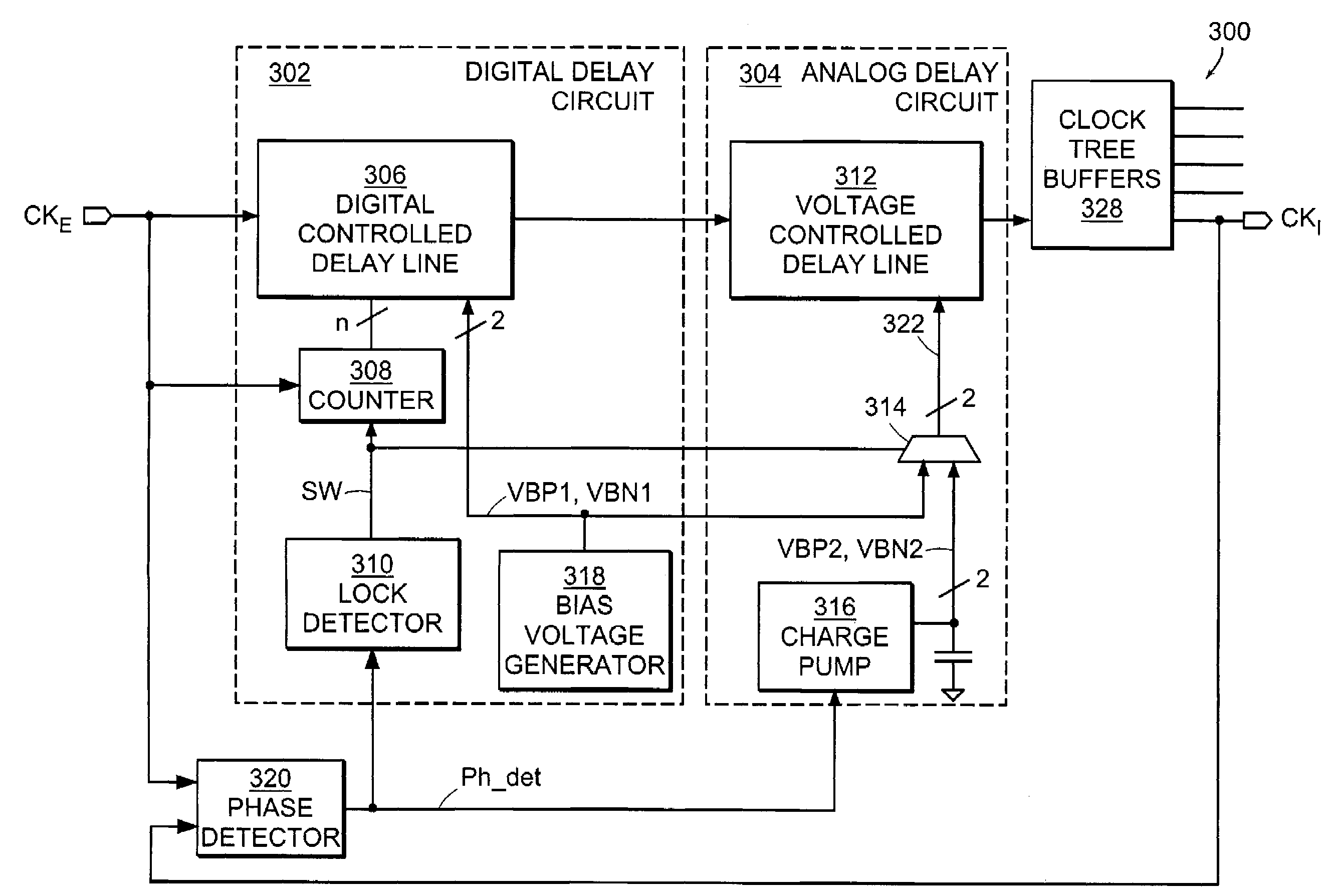
[0025]FIG. 3 is a block diagram of a wide frequency range delay locked loop (DLL) 300 according to the principles of the present invention. The wide frequency range DLL 300 has two domains of operation: a digital domain which includes a digital delay circuit 302 and an analog domain which includes an analog delay circuit 304.

[0026]In a DLL, high accuracy, small silicon area usage and lower power are typically achieved using an analog technique, while good stability and shorter lock times are typically achieved with a digital technique. The wide frequency range DLL 300 combines the two techniques to provide high accuracy, good stability and a fast lock time over a wide frequency range. The digital delay circuit 302 is responsible for coarse phase adjustment during initialization and the analog delay circuit 304 is responsible for fine phase adjustment during normal operation, after coarse phase adjustment is comple...


PUM


Abstract

A delay locked loop operates over a wide range of frequencies and has high accuracy, small silicon area usage, low power consumption and a short lock time. The DLL combines an analog domain and a digital domain. The digital domain is responsible for initial lock and operational point stability and is frozen after the lock is reached. The analog domain is responsible for normal operation after lock is reached and provides high accuracy using smaller silicon area and low power.

Description

BACKGROUND OF THE INVENTION[0001]Many devices such as synchronous dynamic random access memory (SDRAM) and microprocessors receive an external clock signal generated by an external clock source such as a crystal oscillator. The external clock signal received through an input pad on the device is routed to various circuits within the device through a tree of buffer circuits. The buffer tree introduces a common delay between the external clock and each buffered clock.[0002]Typically, a delay locked loop (DLL) with an adjustable delay line is used to synchronize the buffered clock signal with the external clock signal by delaying the external clock signal applied to the buffer tree. The DLL includes a phase detector, which detects the phase difference between the external clock signal and a buffered clock signal. Based on the detected phase difference, the DLL synchronizes the buffered clock signal to the external clock signal by adding an appropriate delay to the external clock signal...

Claims


Application Information

Patent Timeline
Patent Type & Authority Patents(United States)
IPC IPC(8): H03D3/24H03L7/081H03L7/087H03L7/089H03L7/095H03L7/10
CPCH03L7/0814H03L7/0818H03L7/10H03L7/081H03L7/0891H03L7/095H03L7/0816H03L7/087
Inventor VLASENKO, PETERHAERLE, DIETER
Owner MOSAID TECH
Why Eureka
Try Eureka