Electrode, susceptor, plasma processing apparatus and method of making the electrode and the susceptor

a plasma processing apparatus and susceptor technology, applied in the direction of coatings, chemical vapor deposition coatings, metallic material coating processes, etc., can solve the problems of cracking of the electrostatic chuck b>8/b> itself, non-uniform high frequency propagation of plasma generation, etc., to improve the strength of the electrode or susceptor

Inactive Publication Date: 2008-03-04
TOKYO ELECTRON LTD
View PDF22 Cites 81 Cited by
  • Summary
  • Abstract
  • Description
  • Claims
  • Application Information

AI Technical Summary

Benefits of technology

[0023]It is preferred to produce the electrode and/or the susceptor by placing a heater and a porous ceramic in a mold, and pouring a molten base metal into the mold to cast the porous ceramic and the heater in the base metal. According to this manufacturing method, the porous ceramic is infiltrated with t

Problems solved by technology

Thus, warpage or deflection may occur in the electrode itself, posing the problem of making high frequency propagation for plasma generation nonuniform.
For the reasons stated above, cracking may occur in the shower head.
Besides, the pro

Method used


Image

  • Electrode, susceptor, plasma processing apparatus and method of making the electrode and the susceptor
  • Electrode, susceptor, plasma processing apparatus and method of making the electrode and the susceptor
  • Electrode, susceptor, plasma processing apparatus and method of making the electrode and the susceptor

Examples


Embodiment Construction

[0035]An embodiment of an electrode, a susceptor, a plasma processing apparatus, and methods for producing them, which are related to the present invention, will be described in detail based on the accompanying drawings.

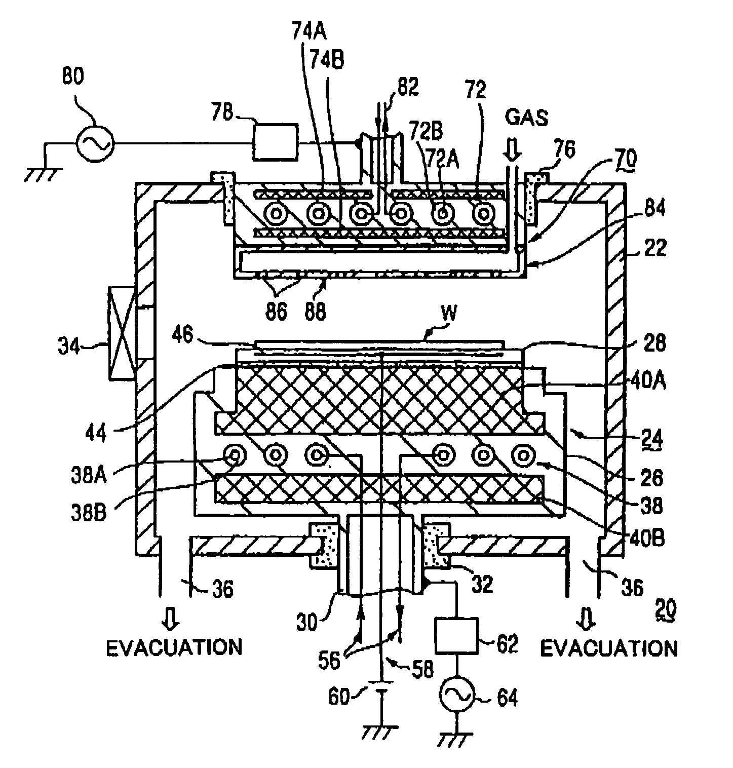
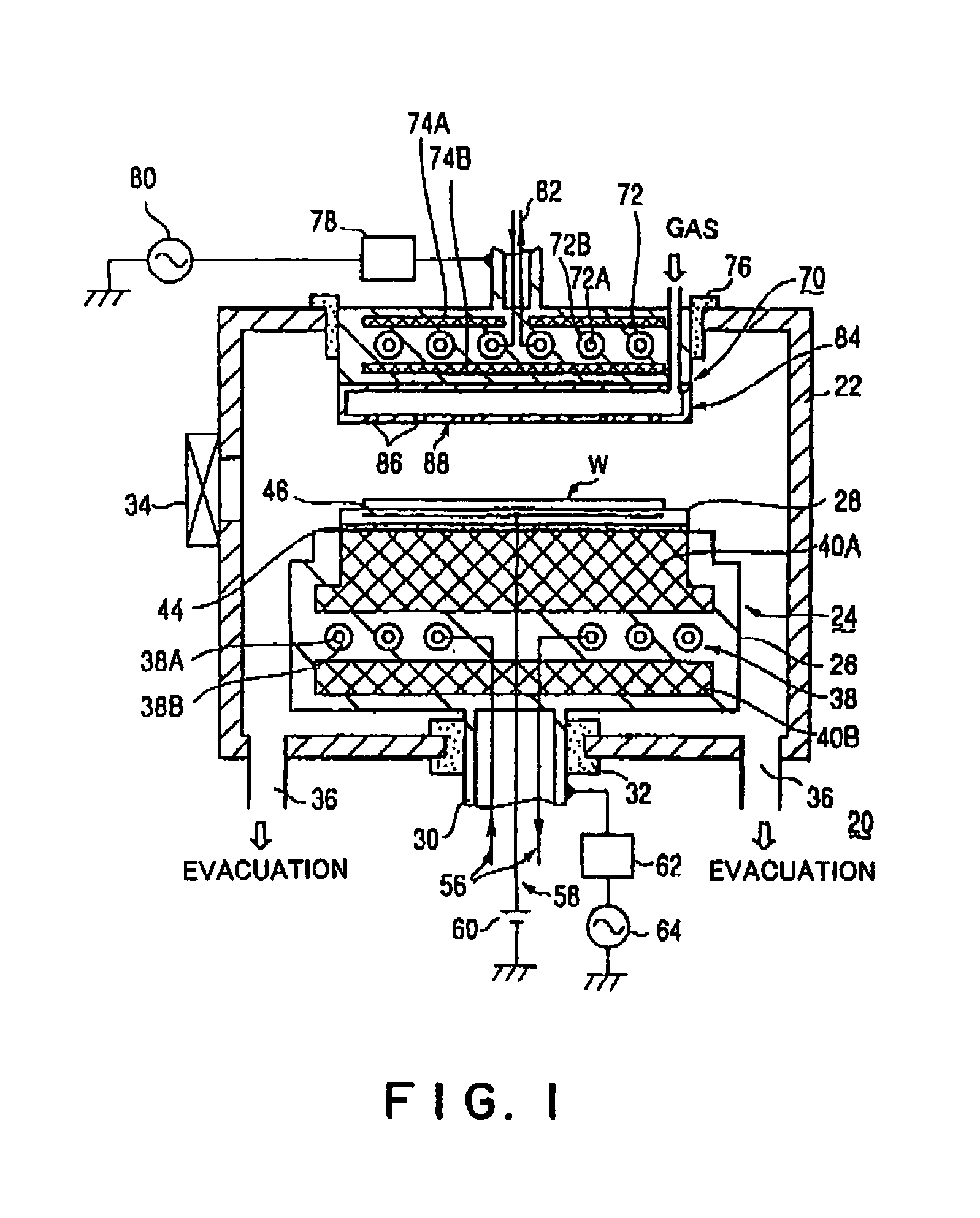
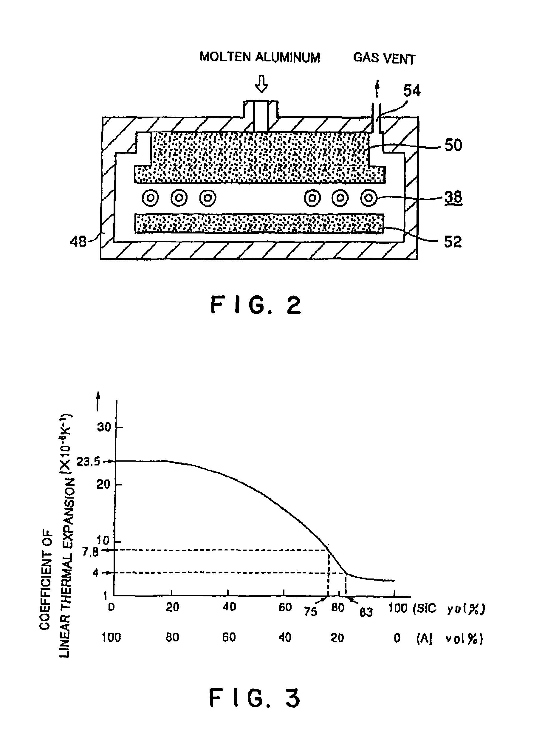
[0036]FIG. 1 is a configurational view showing a plasma processing apparatus as an embodiment of the invention. FIG. 2 is an explanation drawing for illustrating a method for producing an upper electrode in FIG. 1. FIG. 3 is a graph showing the relationship between the content of SiC in aluminum and the coefficient of linear thermal expansion.

[0037]As shown in FIG. 1, a plasma processing apparatus 20 has a cylindrical processing vessel 22, for example, made of aluminum. Provided at a side portion of the processing vessel is a gate valve 34, which is opened and closed when a semiconductor wafer W, i.e., an object to be treated, is carried into and out of the processing vessel 22. Provided at the bottom of the processing vessel 22 is an exhaust port 36, which is connec...


PUM

PropertyMeasurementUnit
Thicknessaaaaaaaaaa
Thicknessaaaaaaaaaa
Diameteraaaaaaaaaa

Abstract

A susceptor 24 includes a heater 38 disposed in a planar state, upper and lower ceramic-metal composites 40A and 40B disposed so as to sandwich the heater 38 from above and from below, and a ceramic electrostatic chuck 28 for attracting and holding an object to be treated, W. The electrostatic chuck is joined to an upper surface of the upper ceramic-metal composite 40A. The electrostatic chuck 28 has nearly the same coefficient of linear thermal expansion as that of the upper ceramic-metal composite 40A. Thus, peeling or cracking of the electrostatic chuck 28 due to the difference in thermal expansion and contraction between the electrostatic chuck 28 and the upper ceramic-metal composite 40A can be prevented.

Description

[0001]This application is a Continuation of PCT International Application No. PCT / JP00 / 02228, filed on Apr. 6, 2000, and claims the priority of Japanese patent application Ser. No. 11 / 99353, filed on Apr. 6, 1999, the content of which is incorporated herein by reference.TECHNICAL FIELD[0002]This invention relates to an electrode, susceptor and a plasma processing apparatus, and methods of making the electrode and the susceptor.BACKGROUND OF THE INVENTION[0003]Generally, a plasma processing apparatus is known as a single wafer process apparatus for applying a predetermined treatment, such as etching, CVD (chemical vapor deposition), or sputtering, to a semiconductor wafer.[0004]In this type of plasma processing apparatus, various treatments are applied to a semiconductor wafer at a relatively high temperature, with the semiconductor wafer being placed on a susceptor in a processing vessel in which a vacuum can be produced. During any of the treatments, it is necessary to maintain the...

Claims


Application Information

Patent Timeline
IPC IPC(8): C23C16/509C23F1/00H01L21/306C23C16/46H01L21/683
CPCH01L21/6831H01L21/68
Inventor KOMINO, MITSUAKIAMANO, HIDEAKIENDO, SHOSUKEFUJISATO, TOSHIAKISASAKI, YASUHARU
Owner TOKYO ELECTRON LTD
Why Eureka
Try Eureka