Hydraulic hybrid vehicle with integrated hydraulic drive module and four-wheel-drive, and method of operation thereof

a hybrid vehicle and hydraulic drive technology, applied in the direction of machines/engines, fluid gearings, propulsion unit arrangements, etc., can solve the problems of hydraulic drive equipment that has not found successful commercial application in on-road, private and multi-passenger vehicles, and implement hydraulic drive equipment in passenger vehicles, so as to reduce the size, weight and/or number of overall components, and reduce weight and cost

Inactive Publication Date: 2008-03-04
GOVERNMENT OF THE US REPRESENTED BY THE ADMINISTRATOR OF THE U S ENVIRONMENTAL PROTECTION AGENCY
View PDF116 Cites 20 Cited by
  • Summary
  • Abstract
  • Description
  • Claims
  • Application Information

AI Technical Summary

Benefits of technology

[0017]According to the principles of the invention, the obstacles in the prior art are alleviated, by reducing the size, weight and / or number of overall components required for creation of a commercially acceptable hydraulic hybrid drive passenger vehicle, and thereby allow packaging in a passenger vehicle, at a reduced weight and cost.
[0022]According to an additional embodiment of the invention, a method for achieving a smooth transition between a 1:1 gear ratio and a high gear ratio (e.g., 3:1) with just one transmission step change is provided. The method includes sensing an increase in demand for motive power from a vehicle, applying an increased amount of torque from a hydraulic motor to an output shaft of the motor, responsive to the increased demand for motive power, transmitting the torque from the output shaft of the hydraulic motor to a differential through an operatively connected multi-speed transmission engaged in a first gear ratio, and distributing the torque to right and left drive axle segments of the vehicle through the differential, the differential being enclosed within a common housing with the hydraulic motor and multi-speed transmission, and the housing being attached to the vehicle.
[0023]The method also includes destroking the hydraulic motor for a selected time interval to temporarily reduce the amount of torque supplied by the hydraulic motor during that time interval, changing the gear ratio of the multi-speed transmission from the first gear ratio to a second gear ratio in conjunction with the time interval, and restroking the hydraulic motor to again increase the amount of torque supplied by the hydraulic motor responsive to a continued demand for motive power from the vehicle.

Problems solved by technology

Although hydraulic drive equipment has been used on commercial and off-road equipment and mobile devices for many years, hydraulic drive equipment has not yet found successful commercial application for on-road, private and multi-passenger vehicles as part of a “hybrid” power train.
Such lack of implementation of hydraulic drive equipment in passenger vehicles has thus far prevailed in the prior art despite the tremendous fuel economy benefits that could be obtained for such vehicles through use of a hydraulic hybrid power train.
As is known in the art, a principal obstacle to implementation of hydraulic drive equipment in passenger vehicles as a hybrid power train is the challenge of packaging the added hydraulic equipment (e.g., pump(s), motor(s), accumulators, hoses) in addition to conventional drive train components (e.g., engine, transmission, differential, etc.) into the very limited space generally available to such components in conventional passenger vehicle frames and styles.
Furthermore, the increase in cost and weight created by the addition of hydraulic equipment to the conventional drive train components in such vehicles somewhat offsets the benefits of a hydraulic hybrid drive train, by reducing the fuel economy benefits of the technology (due to increased vehicle weight) while simultaneously increasing vehicle cost.

Method used


Image

  • Hydraulic hybrid vehicle with integrated hydraulic drive module and four-wheel-drive, and method of operation thereof
  • Hydraulic hybrid vehicle with integrated hydraulic drive module and four-wheel-drive, and method of operation thereof
  • Hydraulic hybrid vehicle with integrated hydraulic drive module and four-wheel-drive, and method of operation thereof

Examples


Embodiment Construction

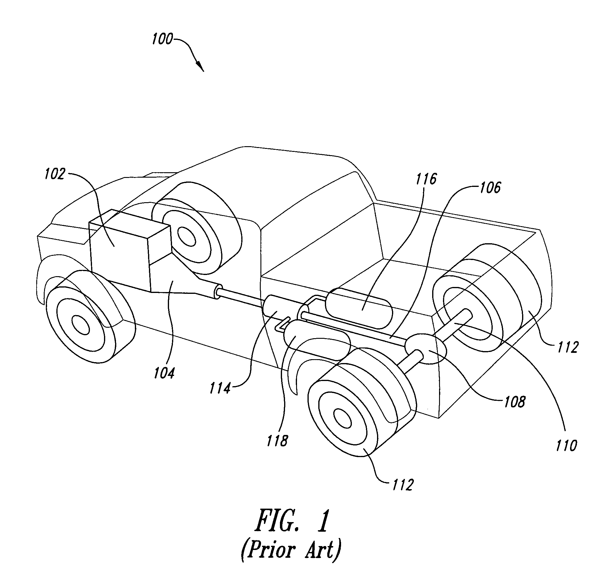
[0030]It will be recognized that a hydraulic hybrid vehicle uses several components that are not found in a conventional vehicle. For example, such vehicles employ at least one, and frequently two or more, pump / motors. In addition, high and low pressure accumulators are used, as well as switching valves and plumbing. Offsetting this additional equipment, in some cases, is the elimination of a drive shaft and a transmission. Nevertheless, it will be recognized that any reduction in weight will result in improved fuel economy.

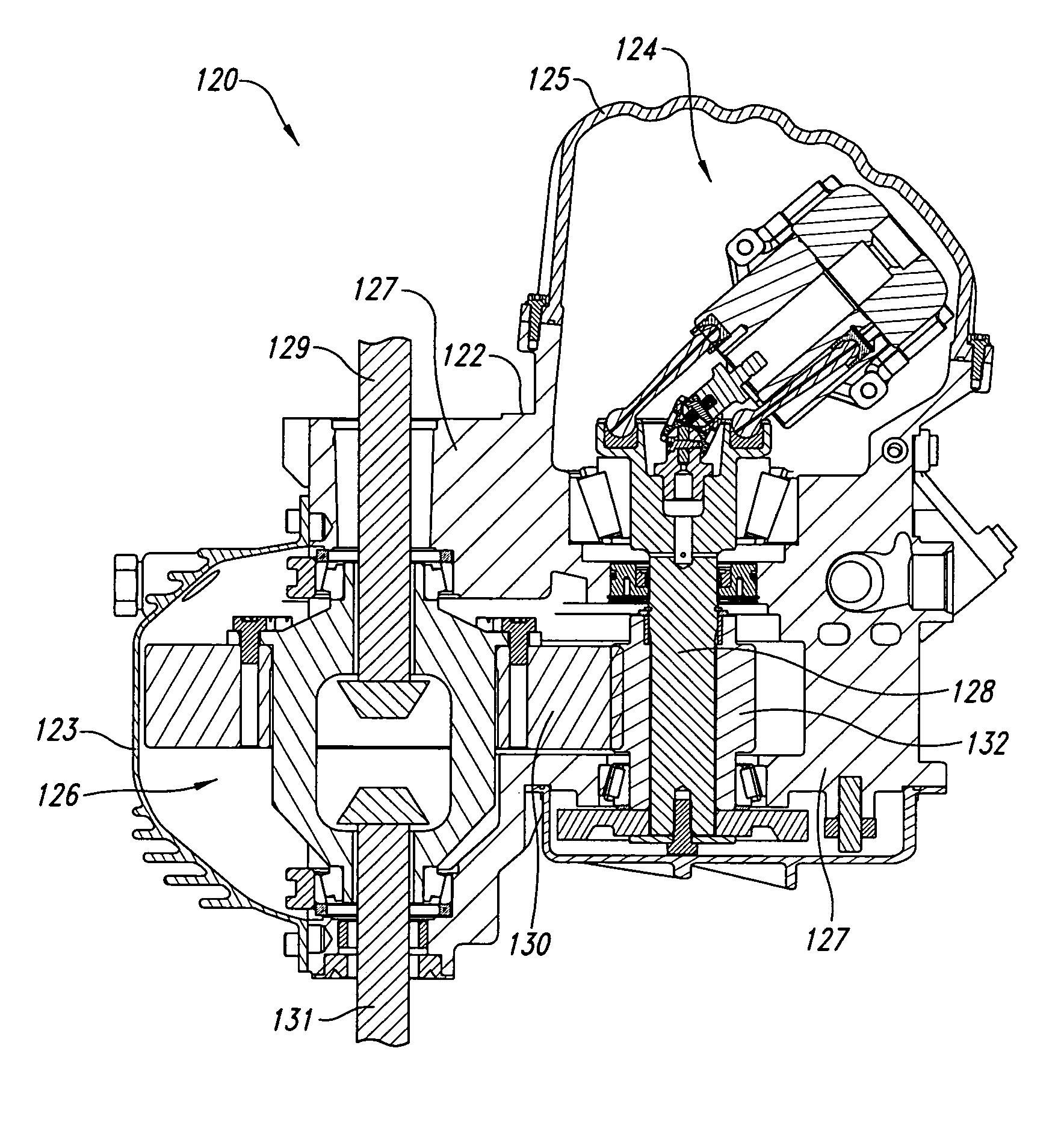
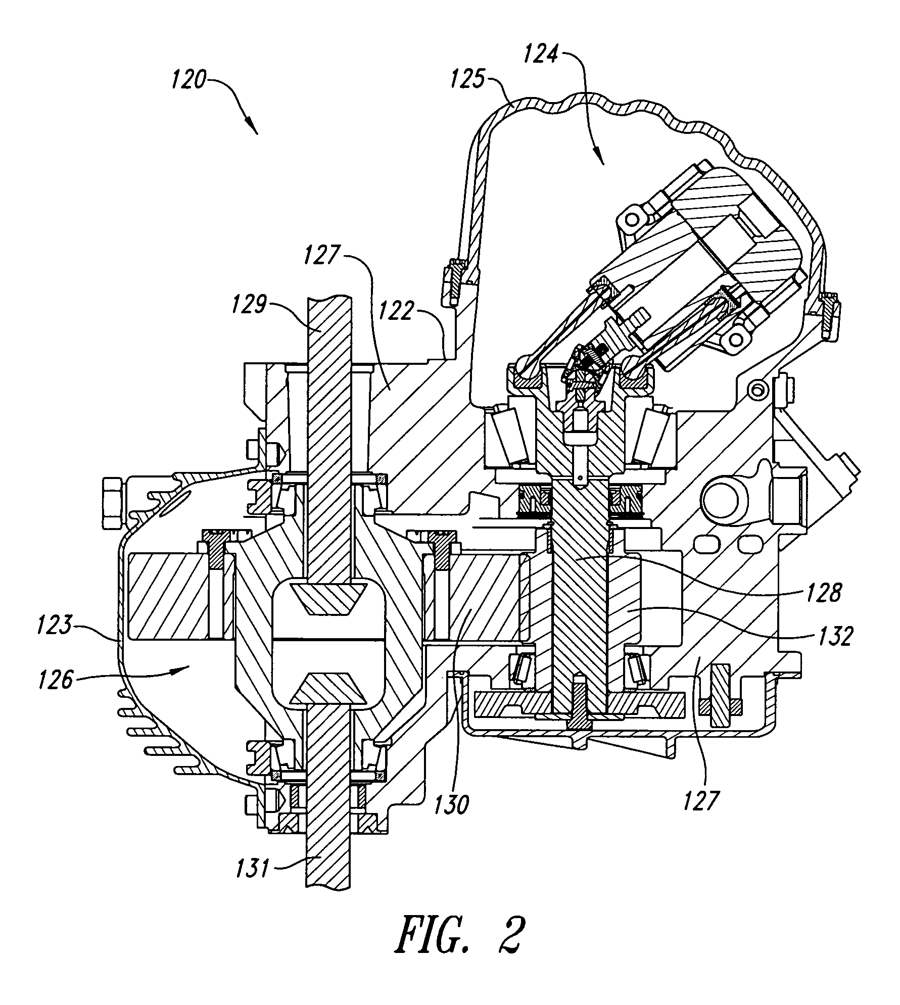
[0031]FIG. 2 illustrates the principles of the invention, according to a first embodiment. As illustrated in FIG. 2, a pump / motor 124 and a differential 126 are incorporated into a common housing 122. The housing 122 includes a differential cover 123, a pump / motor cover 125, and a support frame 127. The output shaft 128 of the pump / motor carries a drive gear 132. The drive gear 132 directly engages the ring gear 130 of the differential 126, which is coupled to ri...


PUM


Abstract

A vehicle includes an integrated drive module coupled to an axle thereof. The module includes a hydraulic motor configured to provide motive power at an output shaft, and a differential for distributing the motive power to right and left portions of the axle. The hydraulic motor and the differential are encased within a common housing. The vehicle may include a second integrated drive module having, within a housing, a second hydraulic motor (or multiple hydraulic motors), and a second differential coupled thereto and configured to distribute motive power to right and left portions of a second axle. The second module may also include a transmission within the same housing. The transmission may be a two speed or other multi-speed transmission. The second module is configured to operate in neutral while power demand is below a threshold, and to engage while the power demand exceeds the threshold. The second module may be configured to remain engaged for full-time four-wheel-drive operation.

Description

CROSS-REFERENCE TO RELATED APPLICATIONS[0001]This application is a continuation-in-part of U.S. patent application Ser. No. 10 / 620,726, “Opposing Pump / Motors,” filed Jul. 15, 2003, which incorporates by reference and is a continuation-in-part of U.S. patent application Ser. No. 09 / 479,844, “Hydraulic Hybrid Vehicle,” filed Jan. 10, 2000, now U.S. Pat. No. 6,719,080 both of which applications are incorporated herein by reference in their entirety.BACKGROUND OF THE INVENTION[0002]1. Field of the Invention[0003]This application is directed to hydraulic hybrid vehicle technology, and in particular to a drive system thereof.[0004]2. Description of the Related Art[0005]Significant interest has been generated, in recent years, in hybrid vehicle technology as a way to improve fuel economy and reduce the environmental impact of the large number of vehicles in operation. The term hybrid is used in reference to vehicles employing two or more power sources to provide motive energy to the vehicl...

Claims


Application Information

Patent Timeline
Patent Type & Authority Patents(United States)
IPC IPC(8): B62M1/10B60K17/10B60K6/12B60K7/00B60K17/356B60K26/02F04B1/24F04B1/32F04B23/06F16H3/091F16H37/08F16H61/4096F16H61/44F16H61/448F16H61/452F16H61/462
CPCB60K6/12B60K17/105B60K17/356B60K41/162F04B1/24F04B1/328F04B23/06F16H3/0915F16H61/4096F16H61/44F16H61/448F16H61/452F16H61/462B60K17/10B60K26/02B60K2741/165B60W2540/10F16H2039/005F16H2200/0034Y02T10/6208Y02T10/76B60K2006/126B60W10/04B60W10/10B60W20/00B60W2710/09B60W2710/105B60W20/14Y02T10/62Y02T10/60
Inventor GRAY, JR., CHARLES L.BARBA, DANIEL W.
Owner GOVERNMENT OF THE US REPRESENTED BY THE ADMINISTRATOR OF THE U S ENVIRONMENTAL PROTECTION AGENCY
Why Eureka
Try Eureka