Cell structure, device and method for gas analysis

a cell structure and gas analysis technology, applied in the field of cell structure, device and method for gas analysis, can solve the problems of more difficult identification, drawbacks of known state-of-the-art cell structure, and difficulty in identification

Inactive Publication Date: 2008-03-04
ENVIRONICS
View PDF14 Cites 3 Cited by
  • Summary
  • Abstract
  • Description
  • Claims
  • Application Information

AI Technical Summary

Benefits of technology

[0033]So it is possible, for example, to control the cell structure of the device according to the invention from the outside of the device wirelessly and / or with the help of a cable, the cell structure being placed, for example, to a fume hood or a similar place isolated from the environment in a certain way. When applicable, the control can be realised wirelessly and partly by cable.

Problems solved by technology

However, the known state-of-the-art cell structure has drawbacks.
In addition, variations in air humidity and temperature have a detrimental influence on the properties of the condenser, which makes the processing of the current signals caused by the ions more difficult and thus causes uncertainty in the forming of the mobility spectrum, which makes the identification more difficult.
Further, the possible presence of aerosol particles in the accumulator can have a detrimental effect on the later stages, such as the mechanical and / or electrical blocking of the next analysis chamber, in which case the operation is made more difficult, and the reliability of the analysis result suffers.
The possible re-suspension and / or related contact charging can also detrimentally transfer the charge to a wrong place.
Especially the ion-induced nucleation triggered by radiation and, for example, the heterogenic nucleation taking place in structural defects on surfaces can in some circumstances cause the formation of particle-shaped material and its aggregation to places detrimental for the identification of ion mobility.
State-of-the-art solutions are further limited by a certain slowness in the changes of voltage so that it is also possible that changes occurring in the sample gas during a single measurement can influence the final result.

Method used


Image

  • Cell structure, device and method for gas analysis
  • Cell structure, device and method for gas analysis
  • Cell structure, device and method for gas analysis

Examples


Embodiment Construction

[0045]A. First Advantageous Embodiment

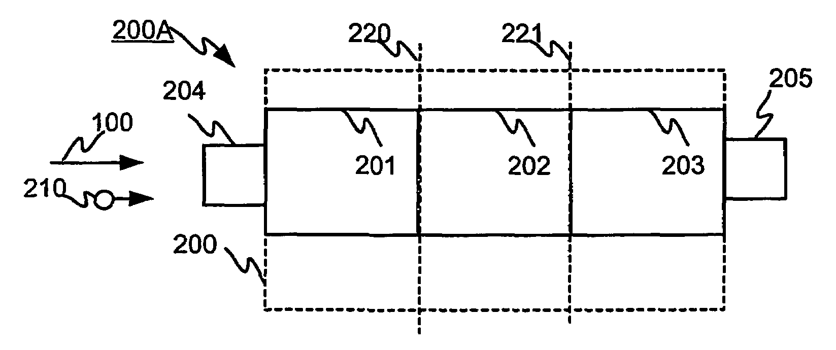
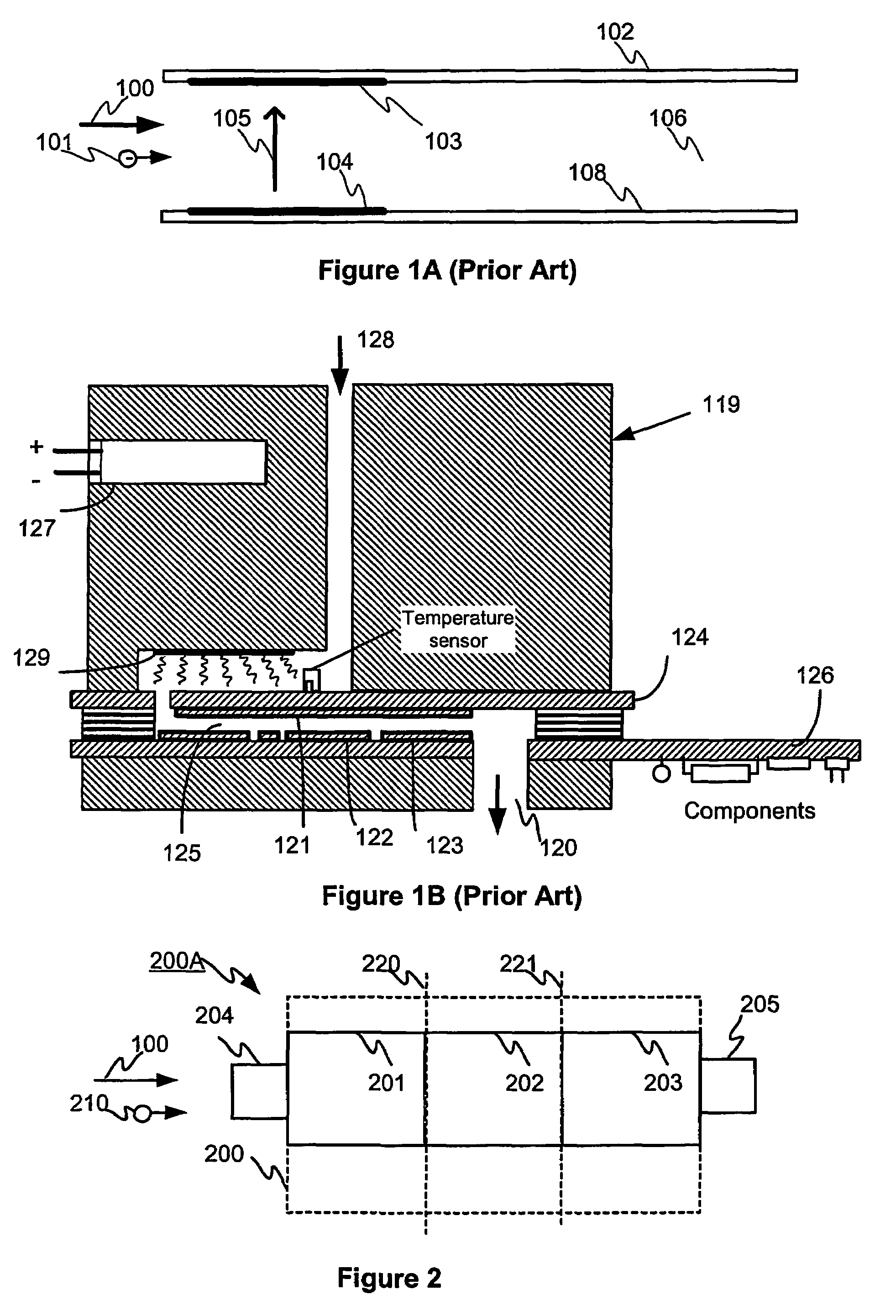
[0046]FIG. 2 shows on a very coarse level an exemplary diagram of the cell structure 200A according to an advantageous embodiment of the invention. The cell structure 200A has a drifting chamber 200 for sample gas, one structural unit 210 of which has been drawn into the figure. The cell structure 200A, its drifting chamber 200, has the reference section 201, the ionisation section 202, and the analysis section 203. For illustrative purposes, the reference section 201 is separated from the ionisation section 202 by the vertical broken line 220. For illustrative purposes, the ionisation section 201 is separated from the analysis section 203 by the vertical broken line 221. The input 204 of the cell structure 200A for the gas sample flow 100 and the output 205 for the analysed sample gas are functionally located at different ends of the cell structure 200A so that the reference section 201, the ionisation section 202 and the analysis section 203 o...


PUM

PropertyMeasurementUnit
heightaaaaaaaaaa
heightaaaaaaaaaa
ion mobilityaaaaaaaaaa

Abstract

The invention relates to a gas analysis based on the mobility of ions. The invention relates to a cell structure of an analysis device, the cell structure comprising the reference cell (201), the ionisation section (202) and the analysis cell (203) for identifying the electric mobility of ions. The invention also relates to a method for identifying the ions. Further, the invention relates to a system for identifying the ions.

Description

OBJECT OF THE INVENTION[0001]The invention relates to analysis technique used in spectrometry based on the mobility of ions. The invention especially relates to a cell structure used in the analysis technique of gas, as disclosed in the preamble of the independent claim concerning it. The invention also relates to a device for identifying the substances in flowing gas, as disclosed in the preamble of the independent claim concerning it. The invention also relates to a system for identifying the substances in sample gas, as disclosed in the preamble of the independent claim concerning the system. Further, the invention relates to a method for identifying the substances in flowing sample gas, as disclosed in the preamble of the independent claim concerning it. The invention also relates to a method for measuring the sample gas velocity, as disclosed in the preamble of the independent claim concerning it.DESCRIPTION OF THE TECHNICAL BACKGROUND[0002]Of the structural units of gas, atoms...

Claims


Application Information

Patent Timeline
Patent Type & Authority Patents(United States)
IPC IPC(8): H01J49/40G01N27/62G01F1/7088G01N27/64G01P5/08
CPCG01F1/7088G01N27/622G01P5/08
Inventor ANTTALAINEN, OSMO
Owner ENVIRONICS
Why Eureka
Try Eureka