Image processing apparatus

a technology of image processing and black fine lines, which is applied in the direction of colour separation/tonal correction, digital marking record carriers, instruments, etc., can solve the problems of deterioration of black fine lines, inability to eliminate completely, and inability to reproduce black fine lines. to achieve the effect of improving the reproducibility of black fine lines

Inactive Publication Date: 2008-03-04
MINOLTA CO LTD
View PDF58 Cites 31 Cited by
  • Summary
  • Abstract
  • Description
  • Claims
  • Application Information

AI Technical Summary

Benefits of technology

[0020]The object of the present invention is to correct the phase shift among the elemen

Problems solved by technology

However, there is a case where a reproducibility of a black fine line is deteriorated by the above-mentioned correction of the fraction by the interpolation process in the correction of the phase shift among red, green and blue colors using a color CCD sensor.
As a result, the black fine line becomes greeny or reddish, so that the reproducibility of the black fine line is deteriorated.
This color deviation due to the chromatic aberration in the color copying machine can be suppressed within a small range less than one dot by improving the lens system or other means, but cannot be eliminated completely.
The color deviation due to the chromatic aberration affects particularly the reproducibility of black letters (including a black fine line) badly.
However, if the above-mentioned color deviation due to the chromatic aberration increases, the difference between the maximum and minimum values of the image data of red, green and b

Method used


Image

  • Image processing apparatus
  • Image processing apparatus
  • Image processing apparatus

Examples


first embodiment

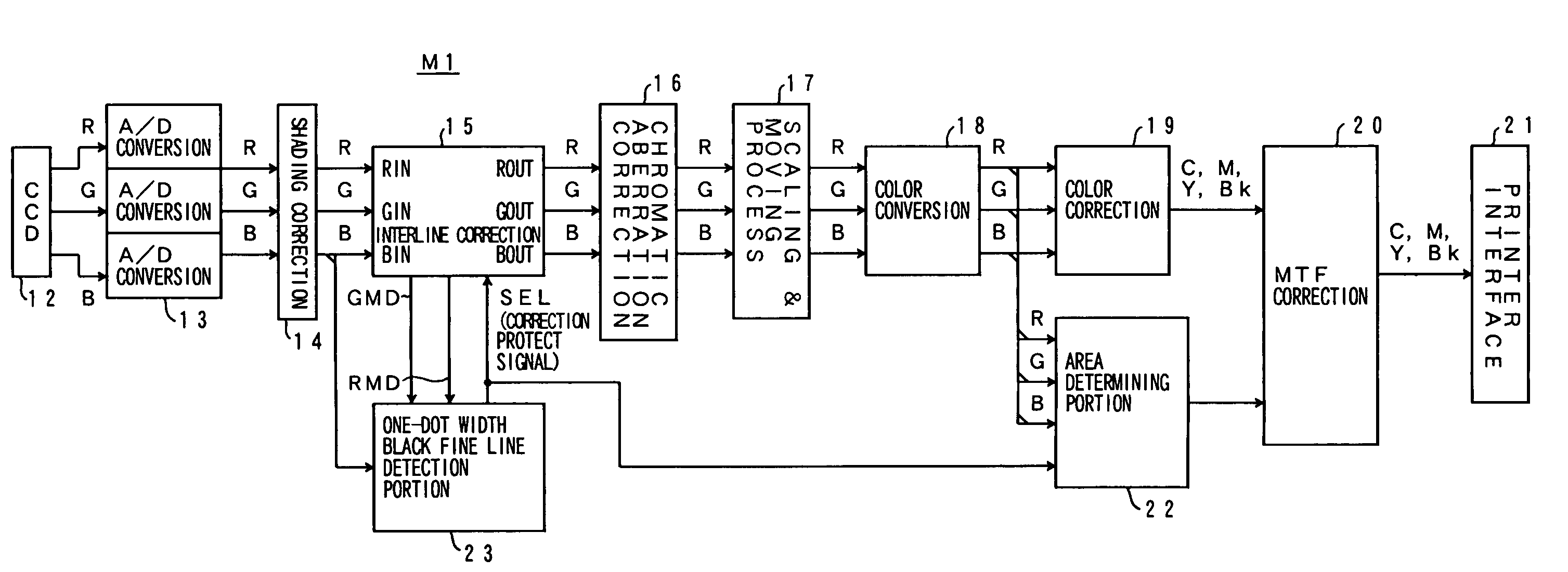
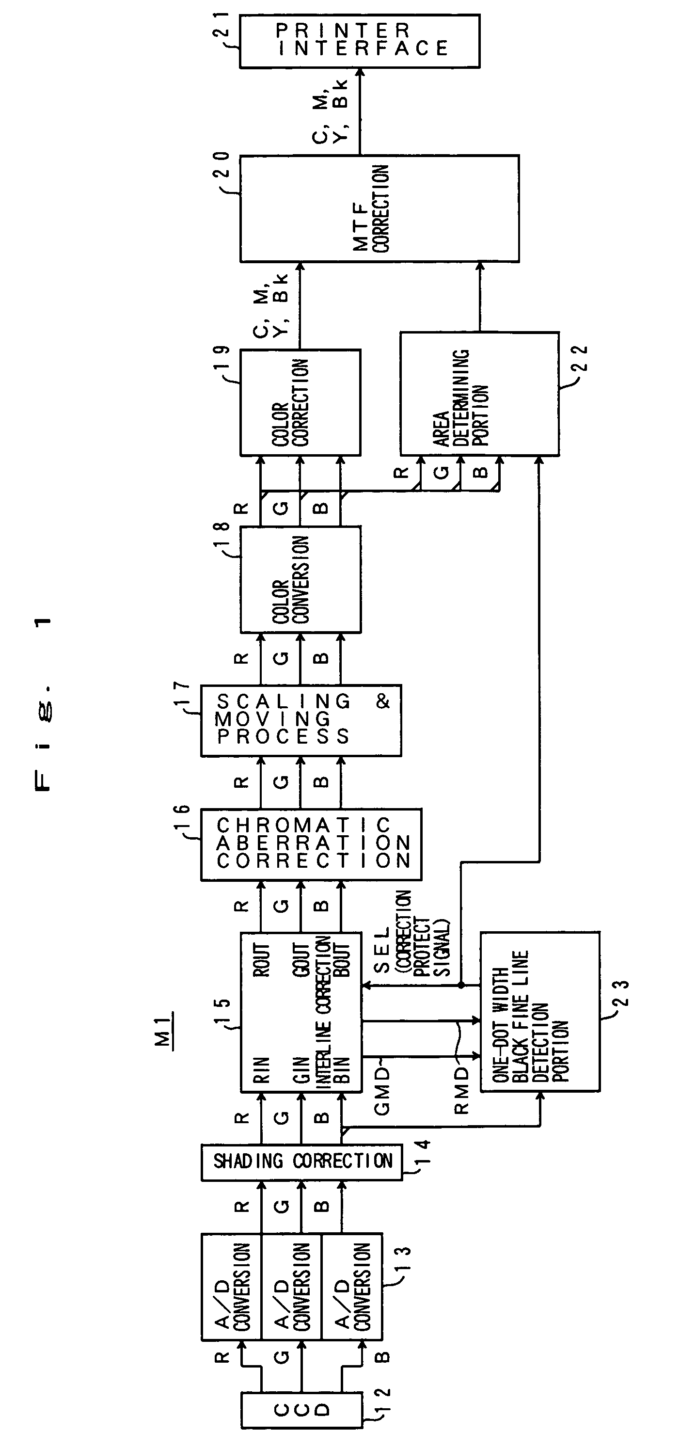
[0058]FIG. 1 is a block diagram showing an overall structure of an image processing apparatus M1 of a first embodiment.

[0059]In FIG. 1, information obtained by contracting and projecting an original image through an optical system is read by a contraction type color CCD sensor 12. The obtained image signals of red (R), green (G) and blue (B) colors are given to an A / D converter 13. The A / D converter 13 converts red, green and blue image signals that are analog signals into red, green and blue image data that are 8-bit digital data (256-step density data). The obtained red, green and blue image data are given to an interline correction portion 15 after shading correction by a shading correction portion 14 in which unevenness of light quantity in the primary scanning direction is corrected.

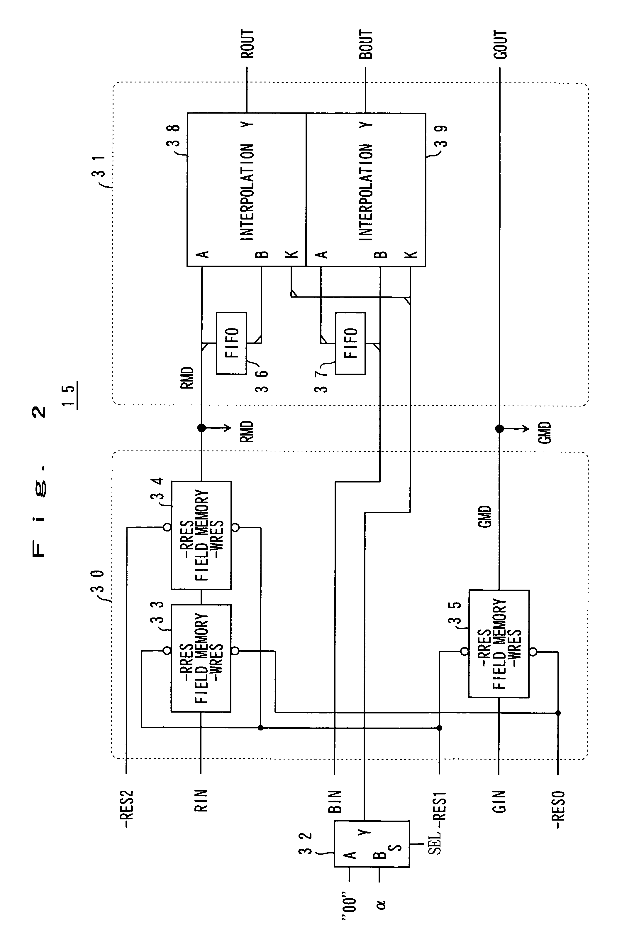
[0060]The interline correction portion 15 is a circuit that corrects a phase shift of the image signal (image data) due to a misregistration of red, green and blue lines of the CCD sensor 12. The in...

second embodiment

[0112]FIG. 11 is a block diagram showing an overall structure of an image processing apparatus M1B of a second embodiment. FIG. 12 is a block diagram showing configuration of an interline correction circuit 15. In each figure of the second embodiment, the element having the same function as in the image processing apparatus M1 of the first embodiment is denoted by the same reference numeral.

[0113]In FIG. 11, the operation and the process of each portion of the image processing apparatus M1B is similar to that explained for the first embodiment with reference to FIG. 1, so the explanation is omitted.

[0114]As shown in FIG. 12, the interline correction portion 15 include three interline correction circuits 15R, 15G and 15B using reference color of red, green and blue respectively, and a correction output portion 15A that outputs image data after corrected by calculating the average for each color of image data that are output from the interline correction circuits 15R, 15G and 15B. Eac...

third embodiment

[0134]The configuration and operation of an image processing apparatus M1C of a third embodiment are similar to those of the second embodiment explained with reference to FIG. 11, so the explanation of them is omitted.

[0135]FIG. 19 shows an example of a circuit of the chromatic aberration correction portion 16. The chromatic aberration correction portion 16 includes interpolation process portions 131R and 131B, an interpolation coefficient setting portion 132, chroma value generation portions 133A–133E, and data selection portions 134R and 134B. The interpolation process portions 131R, 131B and the data selection portions 134R, 134B are provided for each of the red image data and the blue image data, but are not provided for the green image data. The green image data that has a high visibility are not processed the interpolation, and the input green image data are passed to be output data. The red image data and the blue image data are corrected about their phase shift with referenc...


PUM


Abstract

An image processing apparatus includes a first sensor having a plurality of reading elements arranged in the primary scanning direction, a second sensor disposed in parallel with the first sensor and by a predetermined lines in the secondary scanning direction, an integral correction portion for correcting a time difference of data output due to a position difference between the first sensor and the second sensor by a line unit, and a fractional correction portion for correcting a time difference of data output due to a position difference between the first sensor and the second sensor by a sub line unit. Thus, the correction of the phase shift between element arrays can be performed as precisely as possible and the reproducibility of a black fine line is increased.

Description

[0001]This application is based on Japanese Patent Application No. 25733 / 1999 filed on Feb. 3, 1999, No. 38057 / 1999 filed on Feb. 17, 1999, No. 74836 / 1999 filed on Mar. 19, 1999, and No. 87549 / 1999 filed on Mar. 30, 1999, the contents of which are incorporated herein by reference.BACKGROUND OF THE INVENTION[0002]1. Field of the Invention[0003]The present invention relates to an image processing apparatus that is mounted in a digital color copying machine or other equipment. More specifically, the present invention relates to an interline correction process for correcting a misregistration among red, green and blue colors in the secondary scanning direction of a contraction type color CCD sensor. The present invention also relates to a chromatic aberration correction for correcting a phase shift in the primary scanning direction among image data of red, green and blue colors due to a chromatic aberration of a lens system.[0004]2. Description of the Prior Art[0005]An image reader port...

Claims


Application Information

Patent Timeline
IPC IPC(8): G06F15/00G03F3/08H04N1/46
CPCH04N1/46H04N1/48
Inventor SUZUKI, HIROYUKIISHIGURO, KAZUHIROTORIYAMA, HIDEYUKI
Owner MINOLTA CO LTD
Why Eureka
Try Eureka