
System and method for circulating power usage information on a closed ring communication path within a multi-node computer system

a computer system and closed ring communication technology, applied in the field of distributed multi-node systems, can solve the problems of reducing the efficiency of the entire system, and pushing the power supply to its capacity limit, so as to achieve maximum accuracy, efficiency and performance.

Inactive Publication Date: 2008-03-04
INT BUSINESS MASCH CORP
View PDF5 Cites 4 Cited by
  • Summary
  • Abstract
  • Description
  • Claims
  • Application Information

AI Technical Summary

Benefits of technology

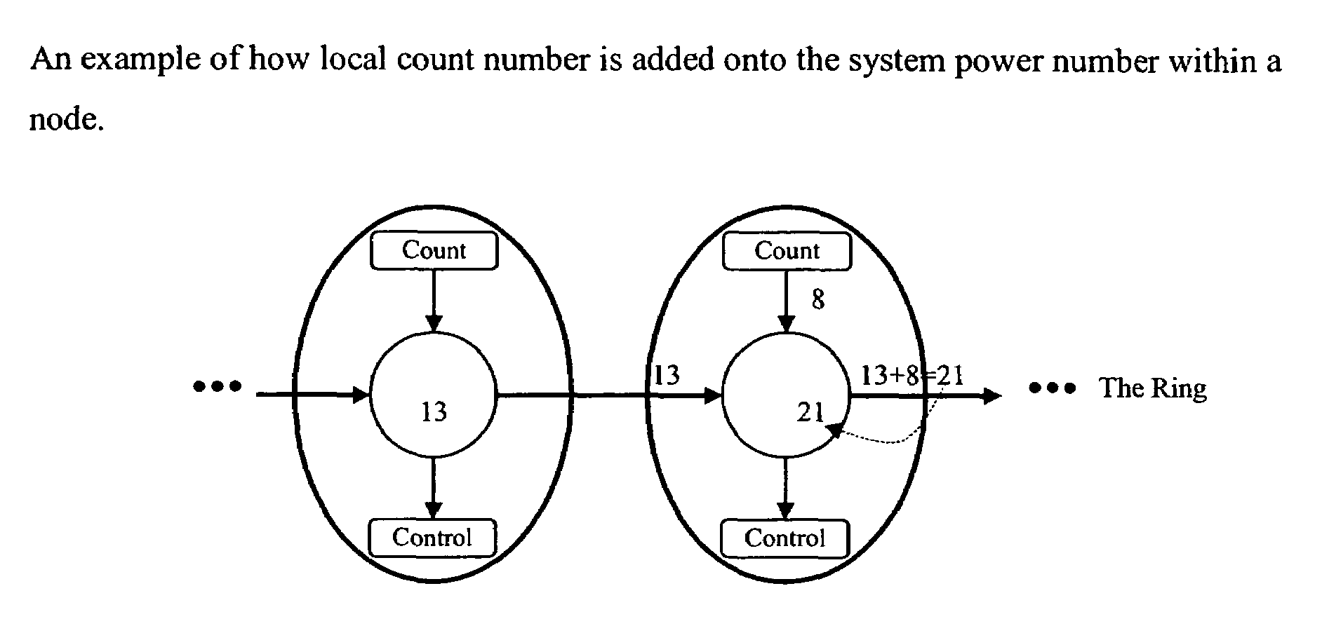
[0009]The shortcomings of the prior art we have discovered are mitigated and additional enhancements are provided through the provision of a method that enables all the power governors within the system to work in concert so that each of the power governors has the knowledge of power consumption within the entire system. So enabled they control and limit the system usage based on a true overall measurement instead of just local measurement. Nevertheless, each of these power governors still has its own way to control / regulate its associated port. This preferred embodiment works well with various numbers of governors installed. It also supports a heterogeneous system, which could drive different current requirement. It is a very flexible design that produces the maximum accuracy, efficiency and performance.

Problems solved by technology

Demands for faster chips and bigger DRAM capacity, etc, are pushing the power supply to its capacity limit.
How to keep the average current consumption low while maintain high system performance and efficiency brings to a significant challenge to today's system design.
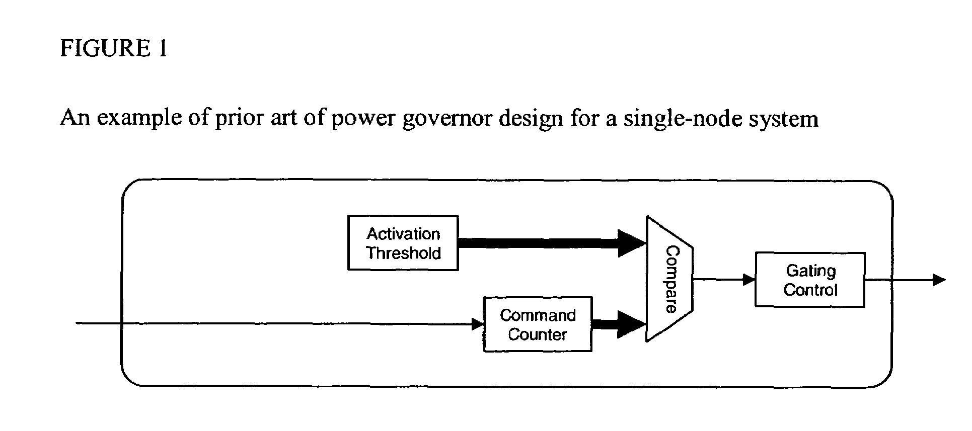
Since those power governors work independently, they do not have the complete awareness of the power usage for the entire system.
However, the average memory activities and total current consumption in the whole system might be still well under the limit.
In this case, the memory performance deteriorates unnecessarily.

Method used


Image

  • System and method for circulating power usage information on a closed ring communication path within a multi-node computer system
  • System and method for circulating power usage information on a closed ring communication path within a multi-node computer system
  • System and method for circulating power usage information on a closed ring communication path within a multi-node computer system

Examples


Embodiment Construction

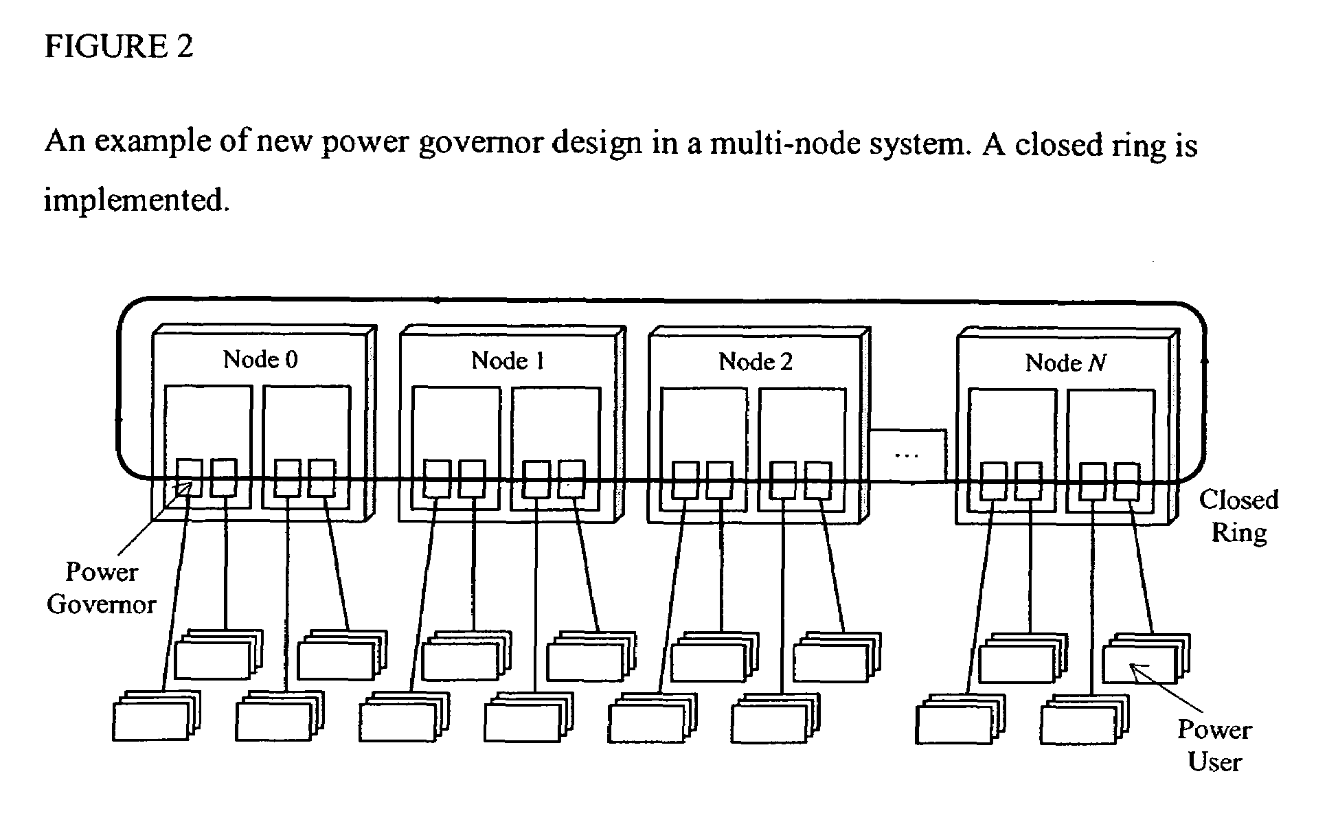
[0022]As shown with reference to FIG. 2, in our preferred embodiment we have provided a method that allows all the power governors in the system to present their local power consumptions to other governors in a computer system. By exchanging the power consumption information, each power governor unit can have the global awareness of the total system power usage. We established a closed-ring communication path that interconnects all the power governors in the system as shown in FIG. 2. We have provided a plurality of nodes (0,1,2,3) arranged in a ring, each having a plurality of memory system controls MSC interfaces to a DRAM memory array. Since it is a closed ring, each of the power governors has its predecessor and successor. There is a System power usage number that circulates in this ring. The number represents the total power measurement of commands that has been utilized so far within the system. The time interval that the number rotates in the ring once is defined as number ci...


PUM


Abstract

A method of regulating power for multi-node computer system components has a closed-ring path that links all the power governors and circulating in the ring is a system power number that represents the power consumption of the entire system. Meanwhile, all the governors keep counting its local power consumption. Each time the number passes a governor, the governor will add its local count onto this number, store this number for future usage, and reset its local count. When the new number returns back to the same power governor, the governor will subtract the new number with its stored number to calculate the overall system power usage within a number circulation period. The system power number overflow problem is also detected with a counter if the incoming number is smaller then the number previously stored. The counter whose counting capacity is greater than the maximum system power usage on all the nodes within a number circulation period. A single number transfer mode and multiple number transfer mode and heterogeneous multi-node components which could have different power usage configurations are employed.

Description

CROSS-REFERENCE TO RELATED APPLICATIONS[0001]This application contains subject matter which is related to the subject matter of the following co-pending applications, each of which is assigned to the same assignee as this application, International Business Machines Corporation of Armonk, N.Y. Each of the below listed applications is hereby incorporated herein by reference in its entirety:[0002]Power Governor for DRAM in a Multi-node Computer System, Kevin Kark and Liyong Wang, U.S. Ser. No. 11 / 081,115, filed concurrently herewith.TRADEMARKS[0003]IBM® is a registered trademark of International Business Machines Corporation, Armonk, N.Y., U.S.A. while other names used herein may be registered trademarks, trademarks or product names of International Business Machines Corporation or other companies.BACKGROUND OF THE INVENTION[0004]1. Field of the Invention[0005]This invention relates to computer system design and particularly to the systems having distributed multi-nodes that consume l...

Claims


Application Information

Patent Timeline
Patent Type & Authority Patents(United States)
IPC IPC(8): G06F1/00
CPCG06F1/32
Inventor WANG, LIYONGKARK, KEVIN W.
Owner INT BUSINESS MASCH CORP
Learn More