
Hydraulic damper element

a technology of damper element and fuel rail, which is applied in the direction of liquid fuel feeder, machine/engine, fuel injecting pump, etc., can solve the problems of reducing or eliminating the ability of effective damping of pressure pulsation, most existing damper elements of fuel rail not suited for use in these high-pressure fuel rails, etc., to reduce the overall emissions of fuel system, reduce the droplet size of fuel, and reduce the effect of eliminating the ability to effectively dampen pressure pulsation

Inactive Publication Date: 2008-03-11
ROBERT BOSCH CORP
View PDF25 Cites 7 Cited by
  • Summary
  • Abstract
  • Description
  • Claims
  • Application Information

AI Technical Summary

Benefits of technology

"The present invention provides an improved damper element for damping pressure pulsations in liquid fuel systems. The damper element is designed to operate effectively in high-pressure fuel rails and can be used in both low and high-pressure fuel rail systems. It has a better change in compressed gas volume per change in fuel pressure ratio and is more efficient in its damping ability. The damper element includes an inner and outer tube with a chamber in between them, and the inner tube has a higher frequency response range and better self-damping characteristics. The damper element is well-suited for use in fuel rail assemblies and is positioned within the fuel rail to damp pressure pulsations. The invention also provides a method for designing the inner and outer tubes using finite element analysis."

Problems solved by technology

Most existing fuel rail damper elements are not suited for use in these high pressure fuel rails.
The existing damper elements may be plastically deformed at these high pressures, thereby reducing or eliminating their ability to effectively dampen pressure pulsations.

Method used


Image

  • Hydraulic damper element
  • Hydraulic damper element
  • Hydraulic damper element

Examples


Embodiment Construction

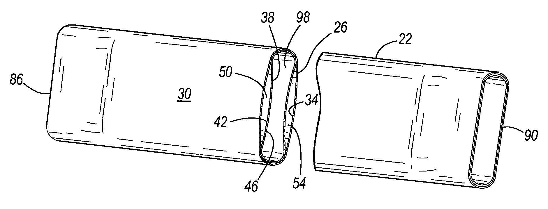
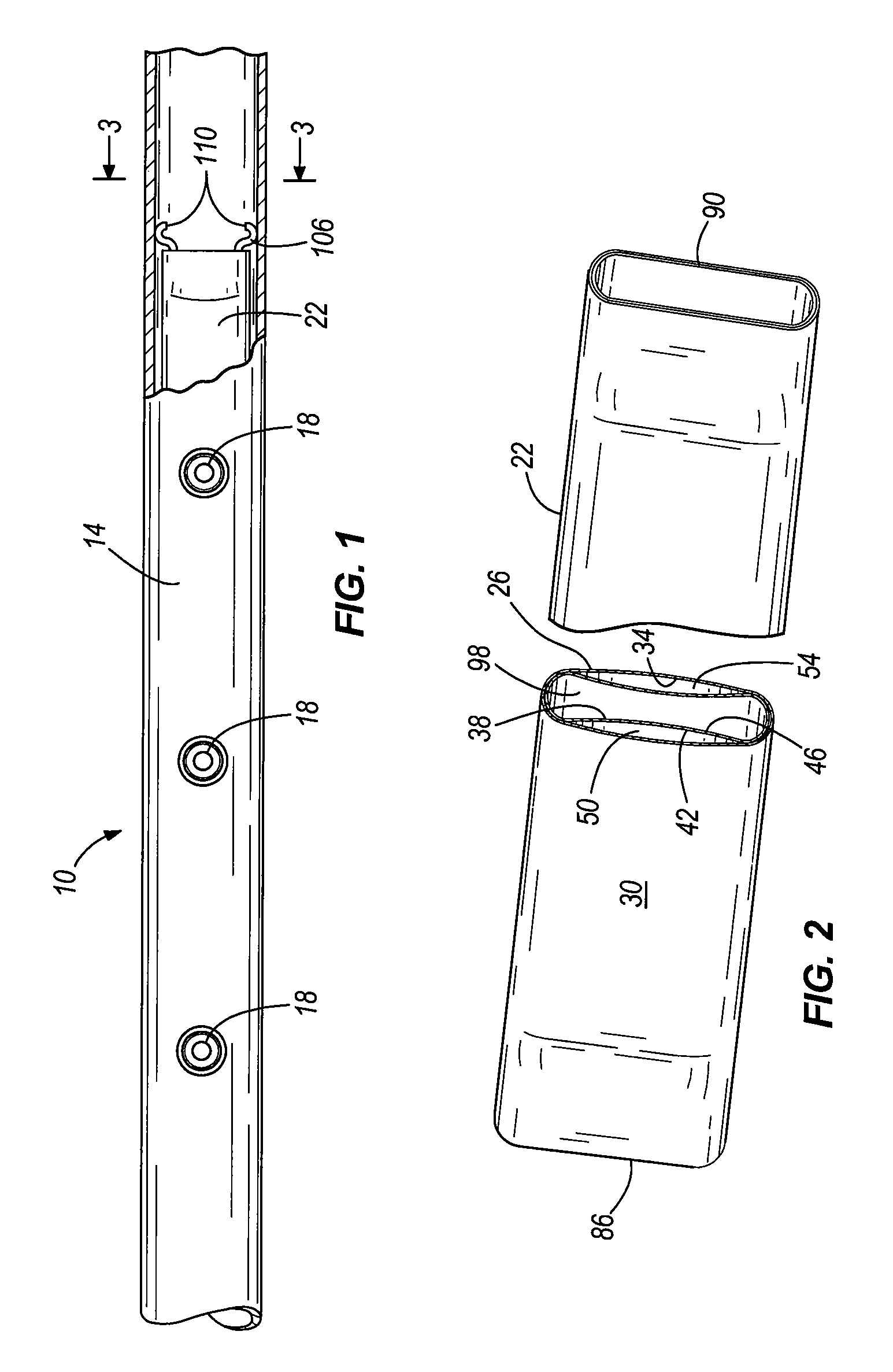
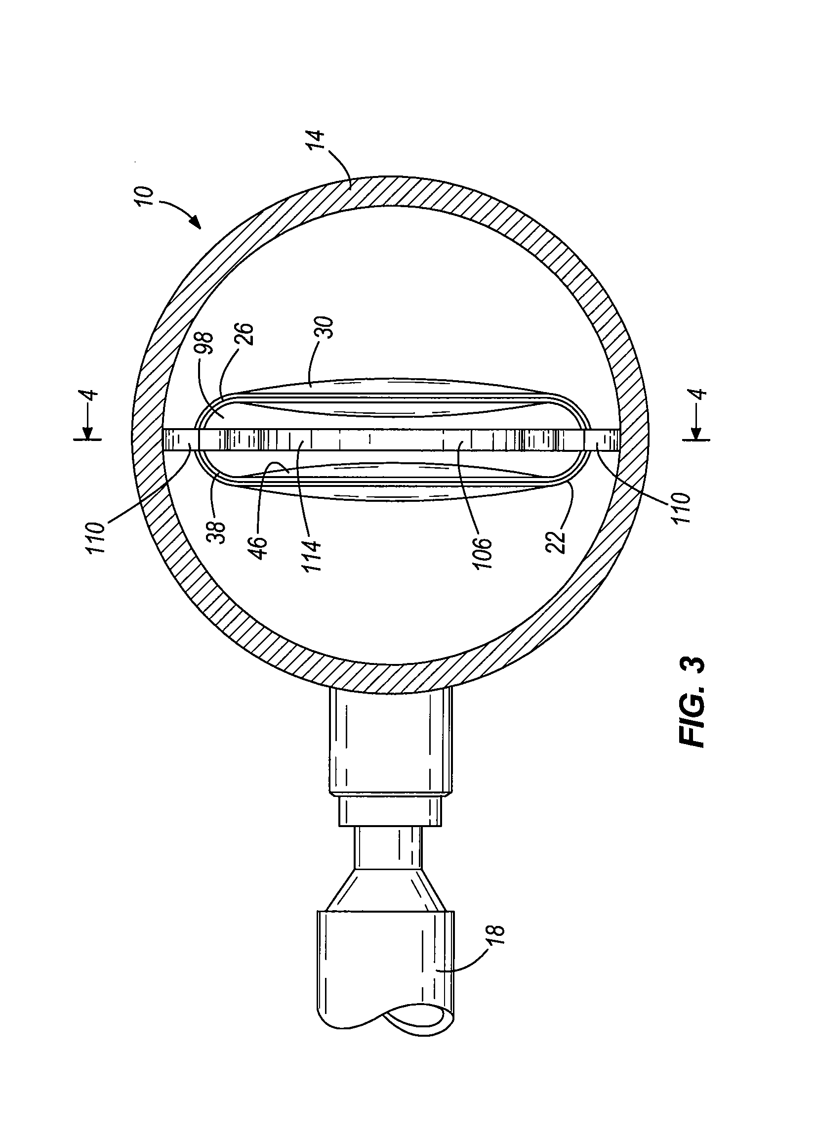
[0026]FIG. 1 illustrates a fuel rail assembly 10 including a fuel rail 14 and a plurality of fuel injectors 18 coupled to the fuel rail 14. The illustrated fuel rail 14 is configured to contain fuel pressurized from about 4 bar to about 150 bar above the ambient pressure. A damper element 22 embodying the invention is positioned inside the fuel rail 14 for damping pressure pulsations in the fuel that are created by the operation of the fuel injectors 18. The damper element 22 is well-suited for operation within the pressure ranges set forth above, and the damping characteristics of the damper element 22 will not be significantly affected by the standard operating temperatures within the fuel rail 14. Additionally, the illustrated damper element 22 can also be used in lower pressure fuel rail systems typically operating at about 2 to about 4 bar above ambient pressure, and provides a more efficient alternative to existing damper elements.

[0027]FIGS. 2-10 illustrate the damper element...


PUM


Abstract

A damper for damping pressure pulsations in a liquid includes an outer tube having an inner surface defining an interior cavity, and an inner tube positioned within the interior cavity of the outer tube. The inner tube includes an outer surface such that at least one chamber is formed between the inner surface of the outer tube and the outer surface of the inner tube for containing a gas. The damper includes an exterior surface configured to be surrounded by the liquid and an interior surface configured to define a passageway through the damper for the liquid. The damper can define at least two, and in one embodiment, four separate chambers for containing a gas. The damper can be part of a fuel rail assembly and is positioned within a fuel rail configured to contain pressurized fuel.

Description

FIELD OF THE INVENTION[0001]The invention relates to fuel rails for the fuel system of an internal combustion engine, and more particularly to damper elements located within the fuel rails for damping pressure pulsations created by the fuel injectors.BACKGROUND OF THE INVENTION[0002]It is known to use damper elements within the fuel rails of fuel-injected fuel systems. The damper elements minimize the otherwise negative effects (e.g., fuel line hammering, improper fuel distribution to injectors, etc.) that can result from pressure pulsations within the fuel rail.SUMMARY OF THE INVENTION[0003]Recently, fuel systems are being designed to include high-pressure fuel rails that operate at pressures ranging from about 4 to 150 bar above the ambient pressure. These high-pressure fuel rails help reduce the droplet size of fuel exiting the fuel injectors, thereby lowering the overall emissions from the fuel system. Most existing fuel rail damper elements are not suited for use in these high ...

Claims


Application Information

Patent Timeline
Patent Type & Authority Patents(United States)
IPC IPC(8): F02M37/04
CPCF02M37/0041
Inventor SIMS, JR., DEWEY M.SHANKARANARAYAN, HURSHA
Owner ROBERT BOSCH CORP
Learn More