Balloon catheter having a multilayered distal tip

Active Publication Date: 2008-03-11
ABBOTT CARDIOVASCULAR
View PDF24 Cites 71 Cited by
  • Summary
  • Abstract
  • Description
  • Claims
  • Application Information

AI Technical Summary

Benefits of technology

[0007]The invention is directed to a catheter having a distal tip with an inner layer formed of a polymeric material having a coefficient of friction and surface energy which are relatively low, such that the

Problems solved by technology

As a result, the wettability of the inner surface of the distal tip by polar liquids

Method used


Image

  • Balloon catheter having a multilayered distal tip
  • Balloon catheter having a multilayered distal tip

Examples


Embodiment Construction

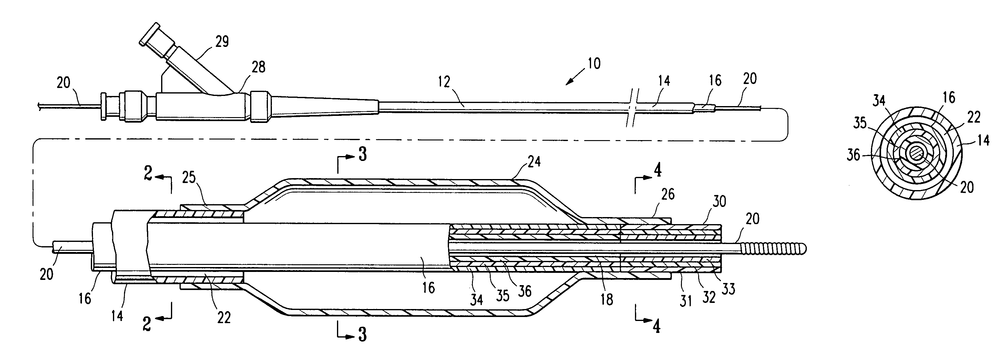
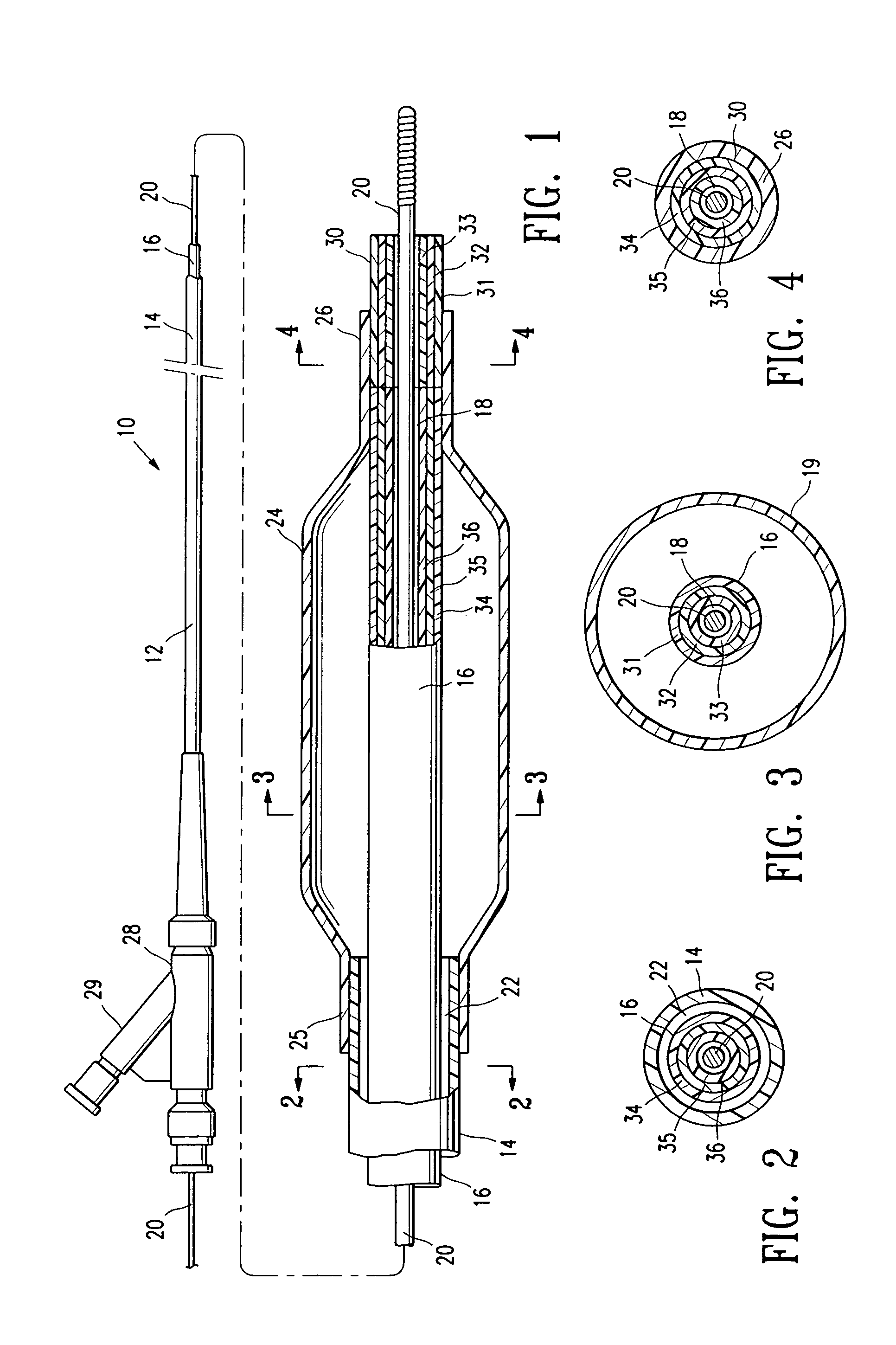
[0019]FIG. 1 illustrates an over-the-wire type balloon catheter 10 embodying features of the invention. Catheter 10 generally comprises an elongated catheter shaft 12, an inflatable balloon 24 on a distal shaft section, and a distal tip 30 at the catheter distal end. In the illustrated embodiment, the shaft comprises an outer tubular member 14 defining an inflation lumen 22 therein, and an inner tubular member 16 defining a guidewire lumen 18 therein configured to slidingly receive a guidewire 20. Specifically, in the illustrated embodiment, the coaxial relationship between outer tubular member 14 and inner tubular member 16 defines annular inflation lumen 22, as best shown in FIG. 2 illustrating a transverse cross section of the distal end of the catheter shown in FIG. 1, taken along line 2-2. In the embodiment illustrated in FIG. 1, the guidewire lumen 18 extends to the proximal end of the catheter. Inflatable balloon 24 has a proximal skirt section 25 sealingly secured to the dis...


PUM


Abstract

A catheter having a distal tip with an inner layer formed of a polymeric material having a coefficient of friction and surface energy which are relatively low, such that the inner layer has a lubricious, non-polar inner surface repulsive to polar liquids. As a result, blood coagulation in the distal tip, and adherence of the distal tip on the guidewire are prevented or minimized.

Description

BACKGROUND OF THE INVENTION[0001]This invention relates generally to catheters, and particularly intravascular catheters for use in percutaneous transluminal coronary angioplasty (PTCA) or for the delivery of stents.[0002]In percutaneous transluminal coronary angioplasty (PTCA) procedures a guiding catheter is advanced in the patient's vasculature until the distal tip of the guiding catheter is seated in the ostium of a desired coronary artery. A guidewire is first advanced out of the distal end of the guiding catheter into the patient's coronary artery until the distal end of the guidewire crosses a lesion to be dilated. A dilatation catheter, having an inflatable balloon on the distal portion thereof, is advanced into the patient's coronary anatomy over the previously introduced guidewire until the balloon of the dilatation catheter is properly positioned across the lesion. Once properly positioned, the dilatation balloon is inflated with inflation fluid one or more times to a pre...

Claims


Application Information

Patent Timeline
IPC IPC(8): A61M29/00
CPCA61M25/104A61M25/1006A61M2025/1093
Inventor HARRIS, MARK E.BAVARO, VINCENT P.WANTINK, KENNETH
Owner ABBOTT CARDIOVASCULAR
Why Eureka
Try Eureka