Vertical-type semiconductor device having repetitive-pattern layer
a semiconductor device and pattern layer technology, applied in the direction of cad circuit design, instrumentation, computer aided design, etc., can solve the problems of increased resistance and consequence, and achieve the effect of small channel resistance and ease of fabrication of semiconductor devices
- Summary
- Abstract
- Description
- Claims
- Application Information
AI Technical Summary
Benefits of technology
Problems solved by technology
Method used
Image
Examples
first embodiment
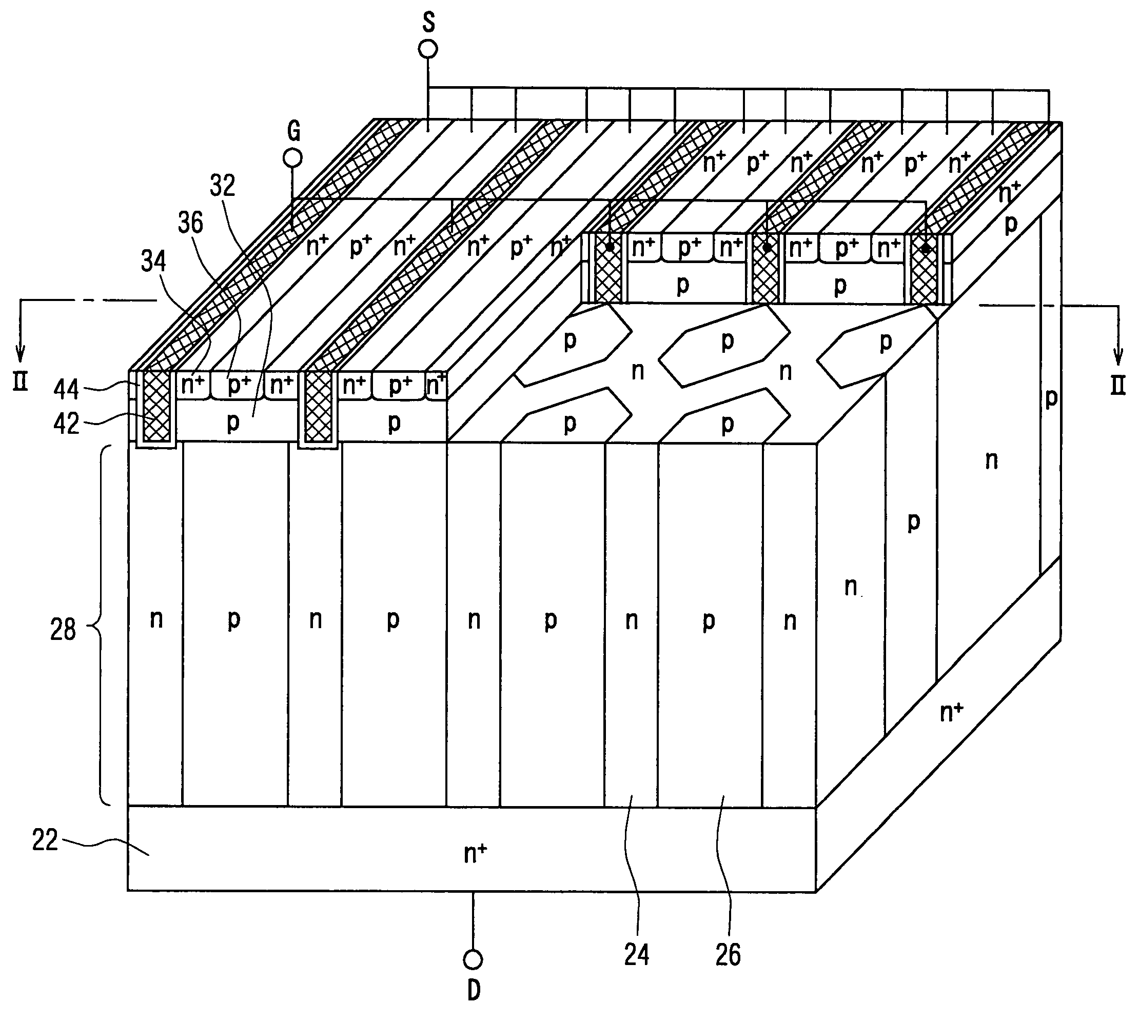
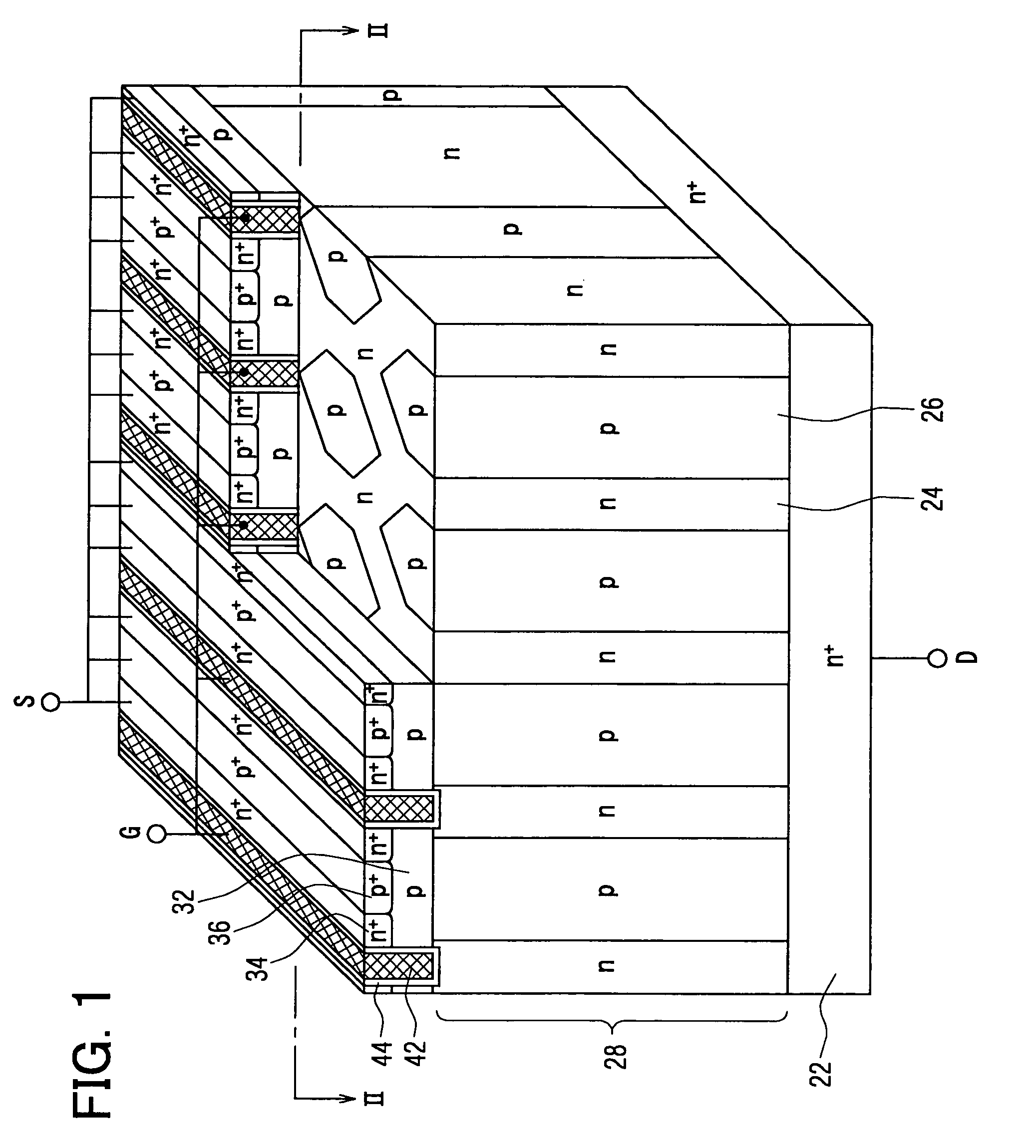
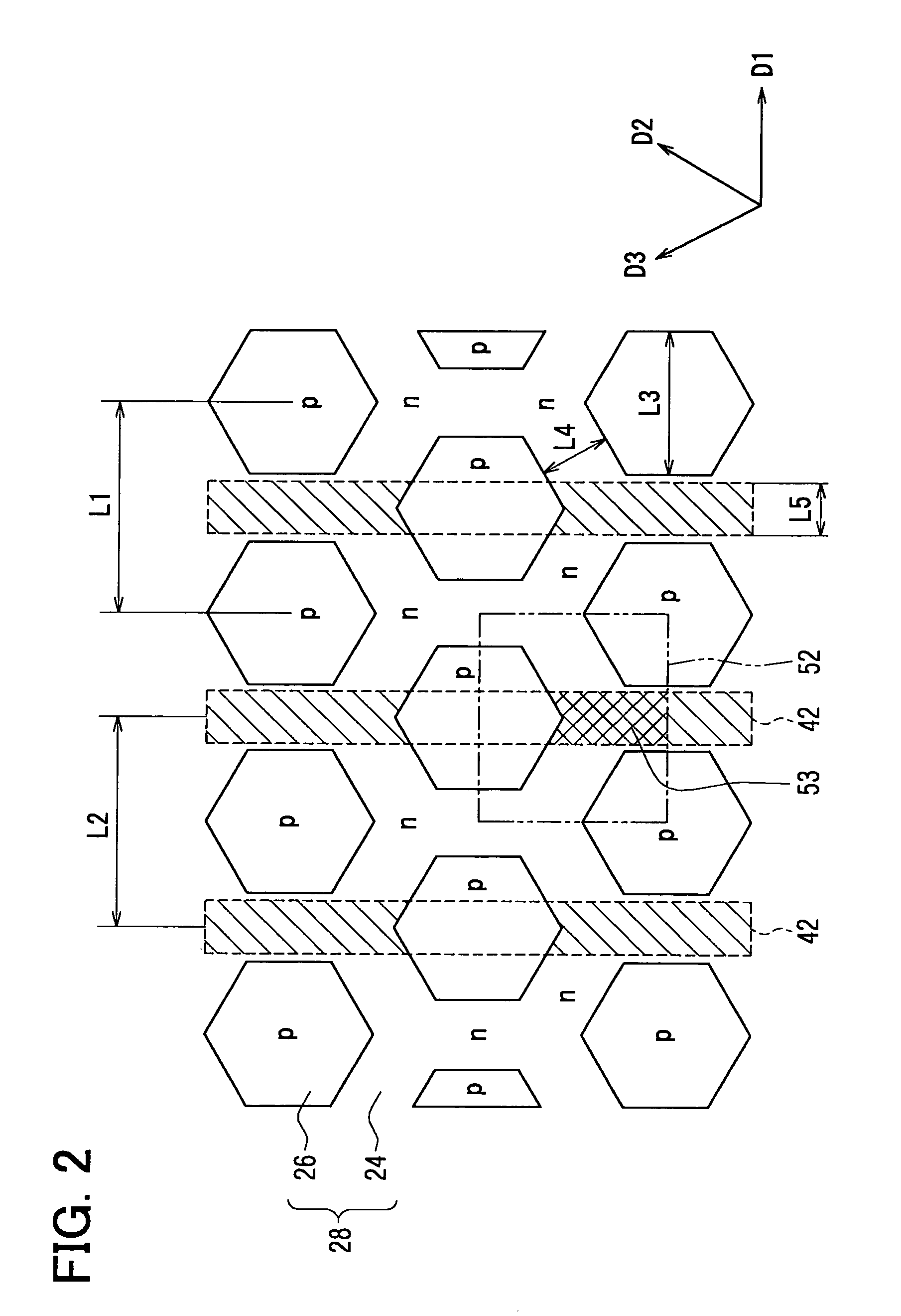
[0049]FIG. 1 is a diagram showing a perspective view of elements composing a semiconductor device including a repetitive-pattern structure of p-type columns 26 and n-type columns 24 on a withstand-voltage layer 28. The semiconductor device has a group of trench gate electrodes 42 each reaching a withstand-voltage layer 28 by penetrating a body layer 32 in contact with the withstand-voltage layer 28. The trench gate electrodes 42 are each created by extending the trench gate electrodes 42 straightly over a long distance on a face parallel to the principal face of the semiconductor device and are arranged repetitively in a direction perpendicular to the longitudinal direction of the group of trench gate electrodes 42 to form parallel stripes. A portion of the body layer 32 is cut out to expose an on-face pattern of the repetitive-pattern structure.
[0050]The semiconductor device shown in FIG. 1 is explained in more detail as follows. The repetitive-pattern structure of the semiconducto...
second embodiment
[0069]FIG. 8 is a diagram showing an on-face pattern of p-type columns 26 and n-type columns 24. In the on-face pattern comprising the p-type columns 26 and the n-type columns 24 in accordance with a second embodiment, the p-type columns 26 each having a square cross section are arranged periodically among the n-type columns 24, being distributed in a layout exhibiting regularity. A distance between the gravity points of any adjacent p-type columns 26 is fixed for all the p-type columns 26. A distance L7 between two sides of a p-type column 26, which face each other, is 3 microns. A distance L8 between two adjacent p-type columns 26 is 1 micron. The p-type columns 26 are arranged repetitively on a face perpendicular to a line connecting main electrodes of a main-electrode pair in two directions like directions D1 and D4 shown in the figure.
[0070]A hatched area 42 enclosed by a dashed line shown in FIG. 8 corresponds to the position of each trench gate electrode 42 in the layout. The...
third embodiment
[0080]A third embodiment is an implementation based on results of examining relations between the size of the overlap area and the channel resistance for the first and second embodiments. It is to be noted that these results are results for a 0-degree inclination angle of the trench gate electrode 42. FIG. 13 is a diagram showing relations between the size of the overlap area common to the trench gate electrode 42 and the n-type column 24 versus the channel resistance. In the diagram, the horizontal axis represents the size of the overlap area whereas the vertical area represents the channel resistance.
[0081]The relations shown in FIG. 13 indicate that the size of the overlap area common to the trench gate electrode 42 and the n-type column 24 is proportional to the channel resistance of the semiconductor device. That is, the variation ratio of the size of the overlap area common to the trench gate electrode 42 and the n-type column 24 is approximately equal to the variation ratio o...
PUM
 Abstract
Description
Claims
Application Information
 - R&D
- Intellectual Property
- Life Sciences
- Materials
- Tech Scout
- Unparalleled Data Quality
- Higher Quality Content
- 60% Fewer Hallucinations
Browse by: Latest US Patents, China's latest patents, Technical Efficacy Thesaurus, Application Domain, Technology Topic, Popular Technical Reports.
© 2025 PatSnap. All rights reserved.Legal|Privacy policy|Modern Slavery Act Transparency Statement|Sitemap|About US| Contact US: help@patsnap.com


