Method for transcoding audio signals, transcoder, network element, wireless communications network and communications system

a technology of transcoding and audio signals, applied in the direction of digital transmission, speech analysis, interconnection arrangements, etc., can solve the problems of reducing the naturalness and intelligibility of speech, reducing the utilization of wideband speech, and pcm speech reduction, so as to achieve the effect of avoiding extra signaling for transcoding during call setup or forwarding, high quality audio, and easy provision of processing capacity

Inactive Publication Date: 2008-03-11
WSOU INVESTMENTS LLC
View PDF15 Cites 22 Cited by
  • Summary
  • Abstract
  • Description
  • Claims
  • Application Information

AI Technical Summary

Benefits of technology

[0015]It is an advantage of the invention that an extra signaling for the transcoding during a call setup or forwarding can be avoided. Terminals and other units can moreover be more simple as they do not need to know and transcode many different codecs. Thus, any terminal or other unit can be employed in the communication according to the invention without requiring extra functionalities. Further, terminals usually also have only a restricted capacity available, and it is easier to provide the processing capacity needed in the network.
[0016]Preferred embodiments of the invention become apparent from the subclaims.
[0017]Preferably, the transcoding comprises generating an at least partially artificial wideband audio signal based on the received narrowband audio signal. This way, the frequency range missing in narrowband audio signals can be supplemented artificially when converting a narrowband audio signal into a wideband audio signal. The wideband audio signal provided to the receiving unit is thus at least partially artificial, but since it is proposed to be generated based on the received narrowband signal, it can be close to the original audio signal. Therefore, the invention allows to provide high quality audio signals, in particular high quality speech, for a wideband terminal user.
[0018]Since a received narrowband audio signal is usually transmitted in coded form, the coded signal is advantageously first decoded to a linear narrowband audio signal before it is converted. After conversion to a linear wideband audio signal, the signal can then be encoded again before it is forwarded to the receiving unit.
[0019]The generation of at least partially artificial wideband signals out of received narrowband signal can be carried out in different ways. It can be based in particular on a statistical evaluation of the received narrowband signals, e.g. by using dedicated codebooks for narrowband and wideband signals and by mapping narrowband codebook values to wideband codebook values for creating a spectrum shaping filter. Alternatively, other statistical mapping methods can be employed. The artificial wideband signal can also based on an up-sampling narrowband audio signals and a subsequent frequency shaping, or on spectral foldings of narrowband audio signals.
[0020]Preferably, the transcoder of the invention comprises in addition to the means for converting a received narrowband audio signal into a wideband audio signal-means for converting a received wideband audio signal into a narrowband audio signal. The latter means can then be employed in case it was determined that a wideband-to-narrowband transcoding is necessary, whenever an audio signal is to be transmitted from a wideband unit to a narrowband unit. This ensures that the transcoder can be employed bi-directionally, which further improves the interoperability between different units. Accordingly, a negotiation of a common narrowband codec in involved units during call setup or call forwarding is not needed. It also enables calls in cases in which a common narrowband codec cannot be found. The method of the invention can be extended accordingly to cover a transcoding in both directions.

Problems solved by technology

This limitation applies to normal PCM (pulse code modulation) speech, which employs a 64 kbit / s coding defined in specification ITU-T G.711, as well as to most of the low-bit rate speech coding methods used in telecommunications systems.
The use of such a narrow frequency rage for speech transmissions reduces naturalness and intelligibility of the speech when presented at the receiving end.
These restrictions have limited to date the utilization of wideband speech.
Thus there will be an annoying quality difference between AMR-WB to AMR-WB and narrowband to AMR-WB calls.
This further reduces the benefits gained with wideband terminals, until such terminals become widely available.
The same problems are encountered also with narrowband services accessed by a user of a wideband terminal, e.g. announcements, voice mail systems, interactive voice interfaces and narrowband audio streaming applications.
Another problem with the transmission of wideband audio signals results from the fact that the extended audio bandwidth used by the wideband terminals requires more transmission capacity.
In addition, the adoption of wideband speech transmission in wireless communications network is difficult due to the lack of established wideband codecs for telecommunication networks.

Method used


Image

  • Method for transcoding audio signals, transcoder, network element, wireless communications network and communications system
  • Method for transcoding audio signals, transcoder, network element, wireless communications network and communications system
  • Method for transcoding audio signals, transcoder, network element, wireless communications network and communications system

Examples


first embodiment

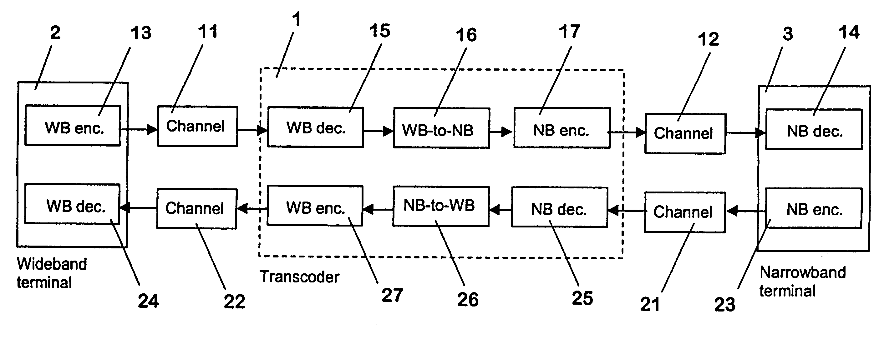
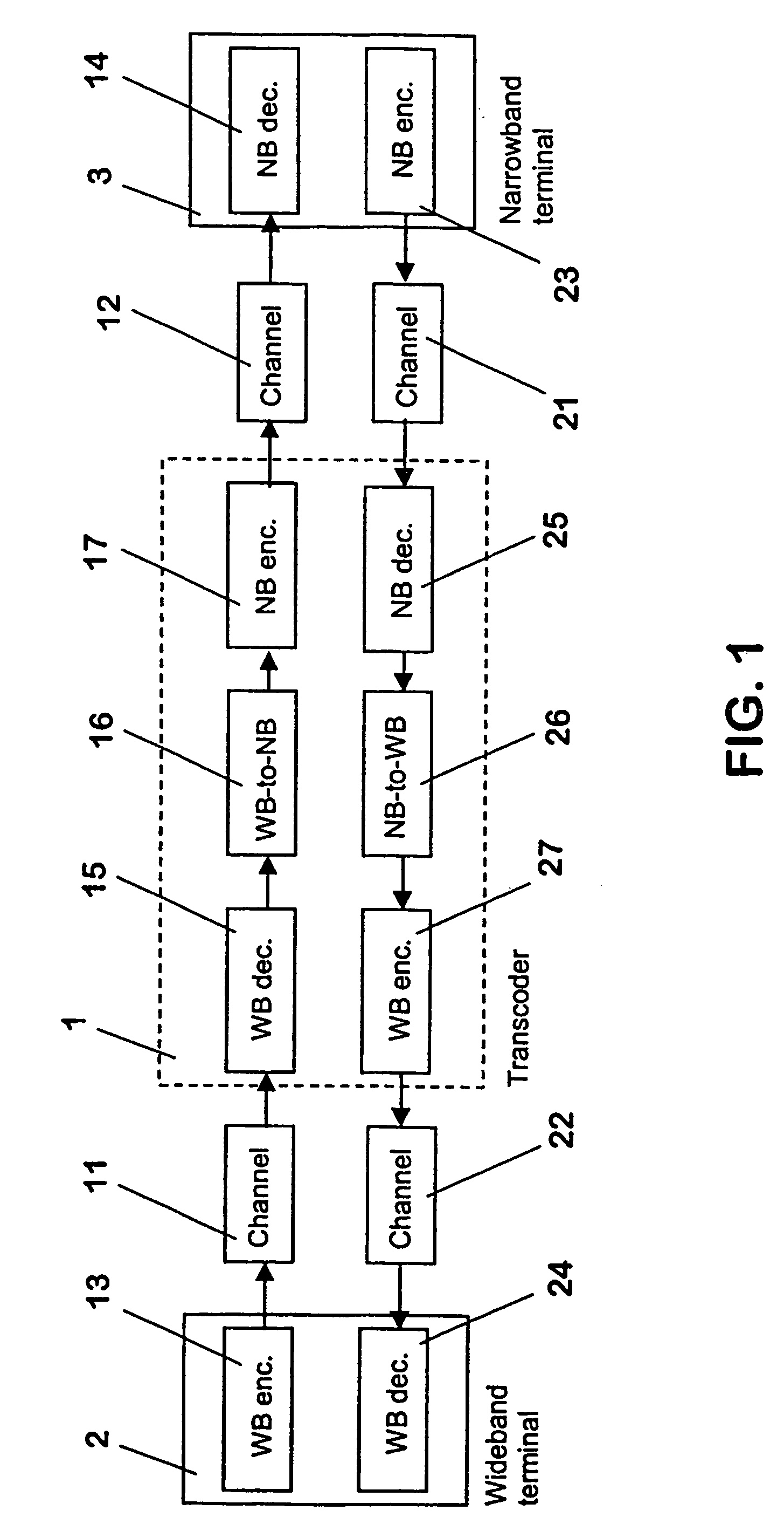
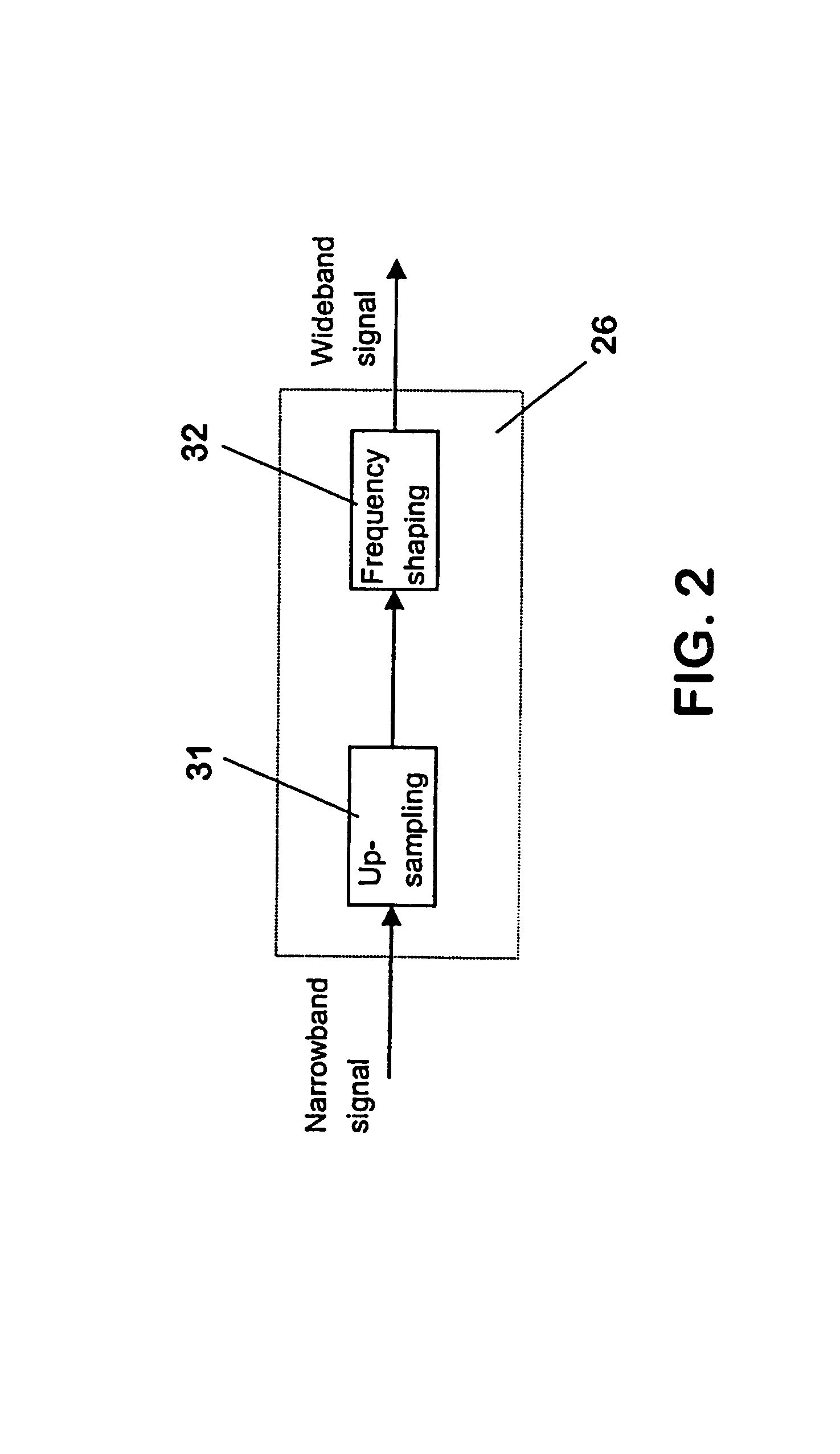
[0050]FIG. 2 is a schematic block diagram of the narrowband-to-wideband converter 26 of FIG. 1. The converter 26 of this embodiment comprises means for up-sampling 31 and means for frequency shaping 32.

[0051]In the first embodiment, the linear narrowband signal is up-sampled without low-pass filtering by the means for up-sampling 31. This generates alias frequency components of the narrowband signal onto the upper band of the wideband signal, i.e. a mirror image of the narrowband signal in the frequency domain. This aliased wideband signal, however, contains excessive distortion which would be subjectively annoying for the user of the receiving wideband terminal 2. Therefore the distortions are smoothed in the means for frequency shaping 32 by attenuating dynamically aliased components based on the narrowband signals. It is to be noted that in particular more attenuation is needed for aliased components with voiced phonemes than for those with unvoiced phonemes.

second embodiment

[0052]Another possibility of converting linear narrowband signals to linear wideband signals is presented in FIG. 3, which illustrates, in form of a schematic block diagram, the narrowband-to-wideband converter 26 of FIG. 1.

[0053]The second embodiment of the narrowband-to-wideband converter 26 comprises a first processing branch with means 33, 34 for up-sampling and lowpass filtering received signals. A second processing branch includes means for a narrowband analysis 35 and means for an upper band signal generation 36. The output of both processing branches is connected to summing means 37, which form the output of the narrowband-to-wideband converter 26 of FIG. 1.

[0054]In the first processing branch of the converter 26, the linear narrowband signal is first up-sampled and then low-pass filtered by the corresponding means 33, 34 in order to obtain a distortion free linear wideband signal of a lower frequency band.

[0055]In the second processing branch of the converter 26, the upper ...


PUM


Abstract

The invention relates to a method for transcoding audio signals in a communications system. In order to improve the inter-operability between units (2,40) capable of handling wideband audio signals and units (3,46) or network components (50) capable of handling narrowband audio signals, it is proposed that first, an audio signal is received in a network element (42) of a communications network via which said audio signal is transmitted. Next, it is determined in said network element (42) whether a transcoding of the received audio signal is required. In case a narrowband-to-wideband transcoding of the received signal is required, the received narrowband audio signal is transcoded into a wideband audio signal in the network element (1,42). The generated wideband audio signal is then forwarded to the receiving terminal (2,40). The invention equally relates to a corresponding communications system and its components.

Description

FIELD OF THE INVENTION[0001]The invention relates to a method for transcoding an audio signal in a communications system, which audio signal is to be transmitted to a receiving unit via a communications network. The invention equally relates to a transcoder, to a network element comprising a transcoder and to a wireless communications network and a communications system comprising a network element with a transcoder.BACKGROUND OF THE INVENTION[0002]In conventional telecommunications systems, the bandwidth employed for transmitting speech signals has typically been limited to a frequency range of about 300 to 3400 Hz with a sampling rate of 8 kHz. This limitation applies to normal PCM (pulse code modulation) speech, which employs a 64 kbit / s coding defined in specification ITU-T G.711, as well as to most of the low-bit rate speech coding methods used in telecommunications systems.[0003]The use of such a narrow frequency rage for speech transmissions reduces naturalness and intelligib...

Claims


Application Information

Patent Timeline
Patent Type & Authority Patents(United States)
IPC IPC(8): G10L19/00G10L21/00H04B1/38H04M7/00G10L21/038H04W88/18
CPCG10L21/038H04W88/181
Inventor KIRLA, OLLILEPANAHO, HENRIKHIMANEN, TEEMU
Owner WSOU INVESTMENTS LLC
Why Eureka
Try Eureka