
Secondary packing arrangement for reciprocating pump polished rod

a technology of reciprocating pump and sealing seal, which is applied in the direction of sealing/packing, fire extinguishers, and well accessories, etc., can solve the problems of increasing wear rate and consumption of barrier fluid, and achieve the effect of increasing the life of elements

Inactive Publication Date: 2008-03-18
BUSCH RANDOLPH A +1
View PDF6 Cites 4 Cited by
  • Summary
  • Abstract
  • Description
  • Claims
  • Application Information

AI Technical Summary

Benefits of technology

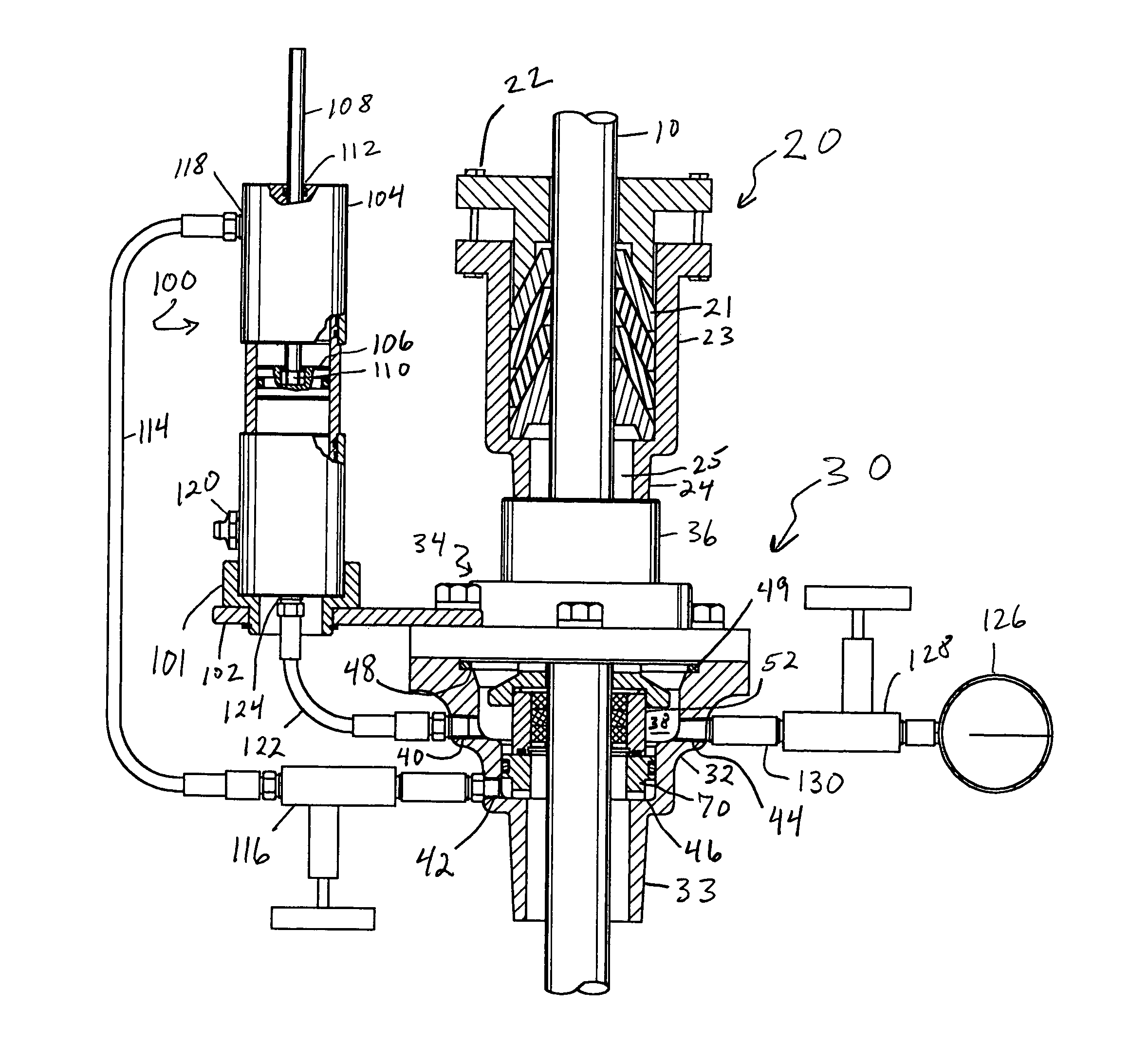
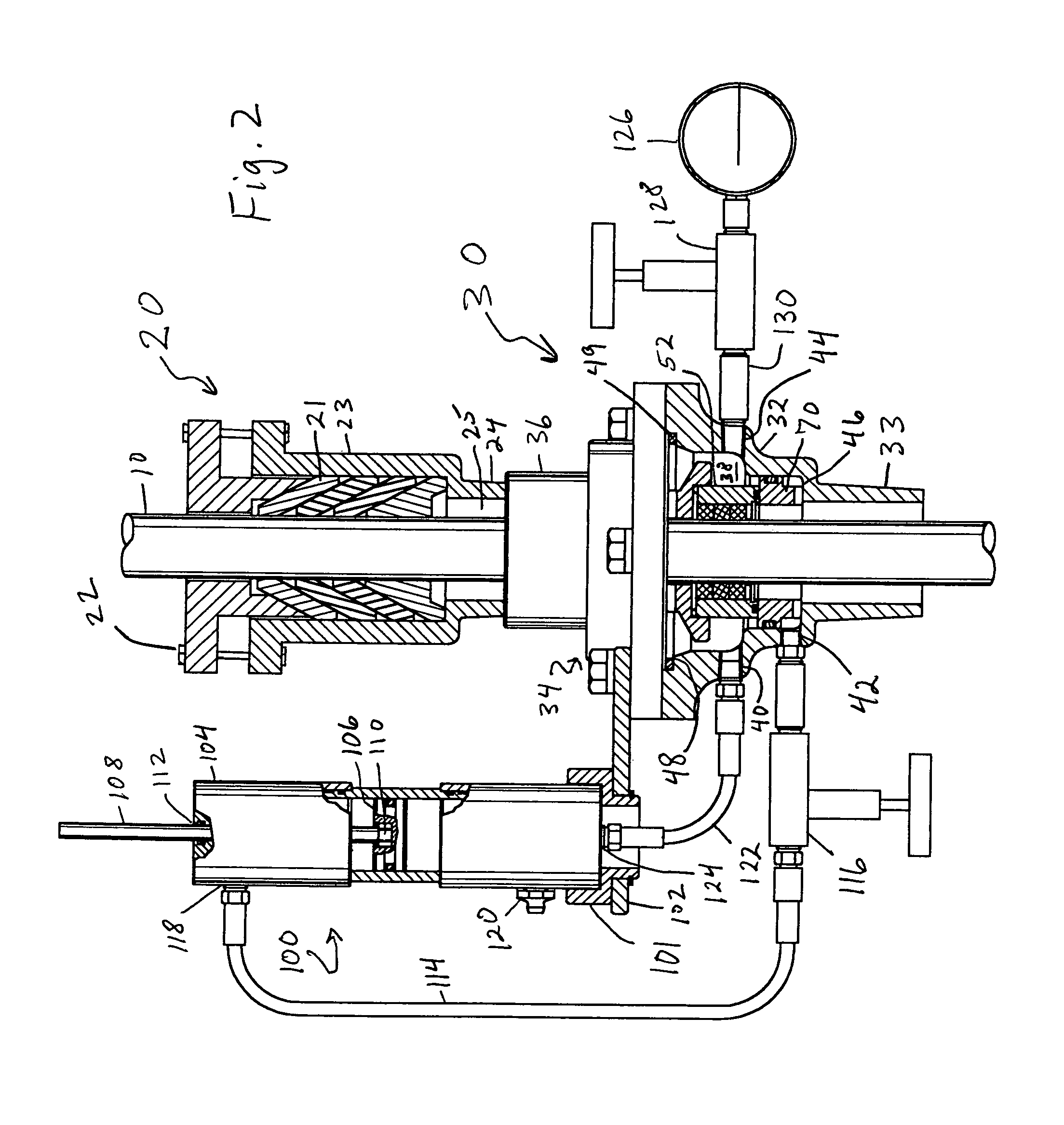
[0008]The present invention overcomes the shortcomings of the prior art by providing apparatus for a secondary packing arrangement that, when used with a conventional stuffing box on a reciprocating plunger type pump having a polished rod, provides a pressure transmitter to create opposing pressures across a packing seal, the pressure being equal to or greater than the corresponding well fluid pressure at any given time during the pumping cycle. In some exemplary embodiments, the secondary packing arrangement includes a first chamber separated by a packing seal from a second chamber formed between the packing seal and the primary packing seal of the conventional stuffing box. The first chamber accepts well fluids, that in some exemplary embodiments are then routed to a pressure transmitter, which transmits the well fluids pressure to a more environmentally acceptable barrier fluid in the second chamber, such that when leakage occurs from the primary packing seal in the stuffing box, the leakage will be barrier fluid. Regulating the opposing pressures across the packing seal in this secondary packing arrangement provides the optimum operating condition for the packing seal elements, thus increasing the life of the elements.
[0009]In the case of the previously described secondary seal arrangement, i.e. the primary and secondary seals, the barrier fluid is sealed from the atmosphere, in some exemplary embodiments, by the primary seal in the conventional stuffing box. The consumption of the barrier fluid will be due mainly to leakage past the primary seal and evaporation of the barrier fluid film from the surface of the polished rod. Leakage past the primary seal is a function of the seal load and wear rate, for a given pressure. Increased seal load improves sealing, but also increases wear rate due to increased friction. The load, or squeeze, of the primary seal is adjusted by threaded bolts, and manually set by the operator. In order to reduce this operator induced uncertainty with respect to the rate of barrier fluid consumption, an alternative seal arrangement has been devised.
[0010]In such an exemplary embodiment (See FIG. 11), an intermediate seal is placed in the lower housing, above the secondary seal, so as to reside between the primary and secondary seals. The load, or squeeze, of the intermediate seal is automatically set upon assembly and is not adjustable. The barrier fluid will then fill the area between the secondary and intermediate seals, and act to regulate the pressure across the secondary seal, just as in the previous seal arrangement. The intermediate seal, although exposed to a pressure differential at least equal to the well fluids pressure, will only come in contact with the clean barrier fluid. The primary seal will remain in place to contain the barrier fluid in the event of intermediate seal wear to the point of leakage. Since the primary seal will not need to be highly loaded, the decreased friction should result in less wear and reduced horsepower requirements.
[0012]Additionally, the secondary packing arrangement of our invention prevents corrosive well fluids from contacting the packing seal elements in the conventional stuffing box, thus increasing the life of the packing seal elements in the stuffing box.
[0013]The application of this technology to sucker rod pumping systems will overcome the universal problem of losing production and polluting the area around the well head.
[0021]In some exemplary embodiments the secondary packing arrangement the packing assembly cylinder has an upper and lower portion, the upper portion having a groove, and further comprises an o-ring positioned within the groove for sealing the cylinder upper portion against the cylinder lower portion, and further comprises a wave spring positioned between the housing top member and the packing assembly cap, such that the housing top member bears upon the packing assembly cap through the wave spring, thereby maintaining a load on the cylinder upper portion and the o-ring.

Problems solved by technology

The consumption of the barrier fluid will be due mainly to leakage past the primary seal and evaporation of the barrier fluid film from the surface of the polished rod.
Increased seal load improves sealing, but also increases wear rate due to increased friction.

Method used


Image

  • Secondary packing arrangement for reciprocating pump polished rod
  • Secondary packing arrangement for reciprocating pump polished rod
  • Secondary packing arrangement for reciprocating pump polished rod

Examples


Embodiment Construction

[0084]The following discussion describes exemplary embodiments of the invention in detail. This discussion should not be construed, however, as limiting the invention to those particular embodiments. Practitioners skilled in the art will recognize numerous other embodiments as well. For a definition of the complete scope of the invention, the reader is directed to the appended claims.

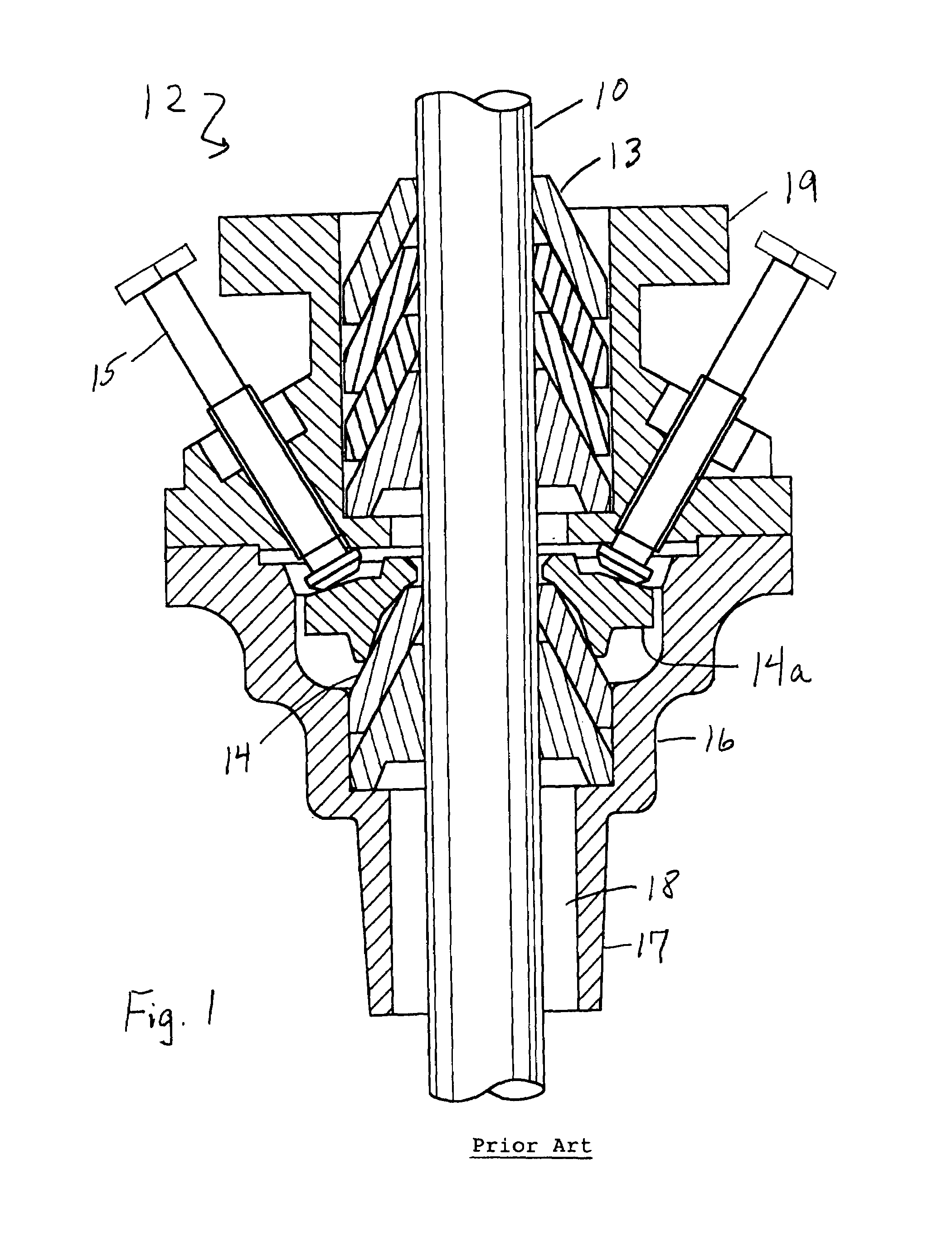
[0085]Referring now to FIG. 1. A typical polished rod 10 extends from the well head and through a conventional double pack stuffing box 12. This stuffing box has two packing seal 13, 14 with each seal having at least two packing seal elements. The packing seal is commercially available and typically referred to as cone or dome packing. Tightening the bolts 15 presses the packing seal 14 against the polished rod by being turned against a packing seal compression ring 14a. The stuffing box has a lower housing 16 with a threaded end 17 for connecting to the well head, such that well fluids will enter the a...


PUM


Abstract

A secondary packing arrangement is provided for use with a well having a reciprocating pump and polished rod, and in combination with a stuffing box, the stuffing box being modified. Packing seals, a barrier fluid and a pressure transmitter cooperate with modified stuffing box components to regulate the pressure on either side of a packing seal. The barrier fluid is contained above the packing seal, with well fluids and accompanying pressures being contained below the packing seal, such that if leakage occurs, relatively clean barrier fluids are leaked instead of well fluids. The pressure across the packing seal is substantially balanced across the packing seal, or the well fluid side pressure is less than the barrier fluid side, thus reducing the occurrence of leakage and extending the life of the packing seal. Sources for the well fluids cooperating with the pressure transmitter include the well's flow line and casing.

Description

CROSS-REFERENCE TO RELATED APPLICATION[0001]This application claims priority from U.S. Provisional Patent Application Ser. No. 60 / 600,183, filed Aug. 10, 2004, the inventors being Randolph A. Busch and Harold H. Palmer.BACKGROUND OF THE INVENTION[0002]1. Field of the Invention[0003]The field of the invention is reciprocating pump polished rod packing seals.[0004]2. Description of Related Art[0005]Over 75 percent of artificially lifted producing oil wells are being produced with sucker rod pumping systems, with the sucker rod string terminating in a polished rod that extends from the well head to the atmosphere. Stuffing boxes, having packing seals about the polished rod, are utilized to prevent well fluids from escaping around the polished rod. Well fluids include corrosive hydrocarbons including salt water and natural gas.[0006]Due to the wear and tear of the moving polished rod, the corrosiveness of some well fluids, and the pressure drop across the packing seal in the stuffing bo...

Claims


Application Information

Patent Timeline
Patent Type & Authority Patents(United States)
IPC IPC(8): E21B19/00
CPCE21B33/08
Inventor BUSCH, RANDOLPH A.PALMOUR, HARROLD H.
Owner BUSCH RANDOLPH A
Learn More