Coupling system useful in placement of implants

a coupling system and implant technology, applied in the direction of prosthesis, blood vessels, surgical forceps, etc., can solve the problems of affecting the positioning of the device, shifting the implant, trauma to the surrounding tissue, etc., and achieve the effect of more flexibility

Active Publication Date: 2008-03-18
WL GORE & ASSOC INC
View PDF73 Cites 114 Cited by
  • Summary
  • Abstract
  • Description
  • Claims
  • Application Information

AI Technical Summary

Benefits of technology

[0010]The invention relates to a coupling device that allows pivoting of the implant at or near the juncture where the implant couples with the distal end of a delivery catheter, which is the coupling device. Specifically, the juncture is designed with a slot, for example, in the shape of a half-circle arc, that allows implant pivoting in a plane along the longitudinal axis of the coupling device. That feature, plus a trapping mechanism that allows implant rotation about the longitudinal axis of the coupling device, provides the much needed flexibility to avoid generating the tension that would otherwise cause bending at the coupling juncture and resulting in distortion of the underlying septum. Accordingly, after being released, the implant will stay where it was intended and the newly freed distal end of the delivery system will have less tendency to spring back and cause trauma to the surrounding tissue.
[0011]According to one aspect of the invention, a coupling or attachment device with a distal end is provided. The coupling device has an assembly that includes at least two prongs. Each of the prongs has a first and a second end. The prongs are connected at their first ends and free at their second ends. The second end of at least one of the prongs is movable from two positions: in an open position, the second ends of the two prongs are apart from each other; in a closed position, the second ends of the prongs are closer to each other than in the open position. Also in the closed position, the second ends of the two prongs define a slot at the distal end of the coupling device. The slot may be used for coupling an object to the coupling device, and is part of the solution to provide more flexibility at the coupling juncture. In one embodiment, the slot is an arc that spans about 180 degrees.

Problems solved by technology

A problem with many of the known delivery systems is that they can often adversely affect positioning of the device that is being implanted, which forces the doctor to estimate and take into consideration such effect when assessing the final implant position prior to releasing the implant.
Upon release of the implant, the tension and torque will affect both the implant and the delivery catheter, causing shifting in the implant position, and possible trauma to the surrounding tissue as the distal end of the catheter springs back to a more relaxed state.
Such shifting in the implant position may result in a less desirable medical result (such as device embolization or a residual leak in the case of septal occluders).
Due to the acute angle of delivery of the septal occluder from the inferior vena cava to the septal wall, the rigid pin-to-pin connection applies tension to the implant and the underlying septum, and compromises precise assessment of the final implant position prior to release of the implant.
This system, however, requires axial rotation of the members with respect to each other to disconnect the delivery device and also provides little flexibility, if any, for the lateral pivoting of the implant at the point it is attached to the delivery device.

Method used


Image

  • Coupling system useful in placement of implants
  • Coupling system useful in placement of implants
  • Coupling system useful in placement of implants

Examples


Embodiment Construction

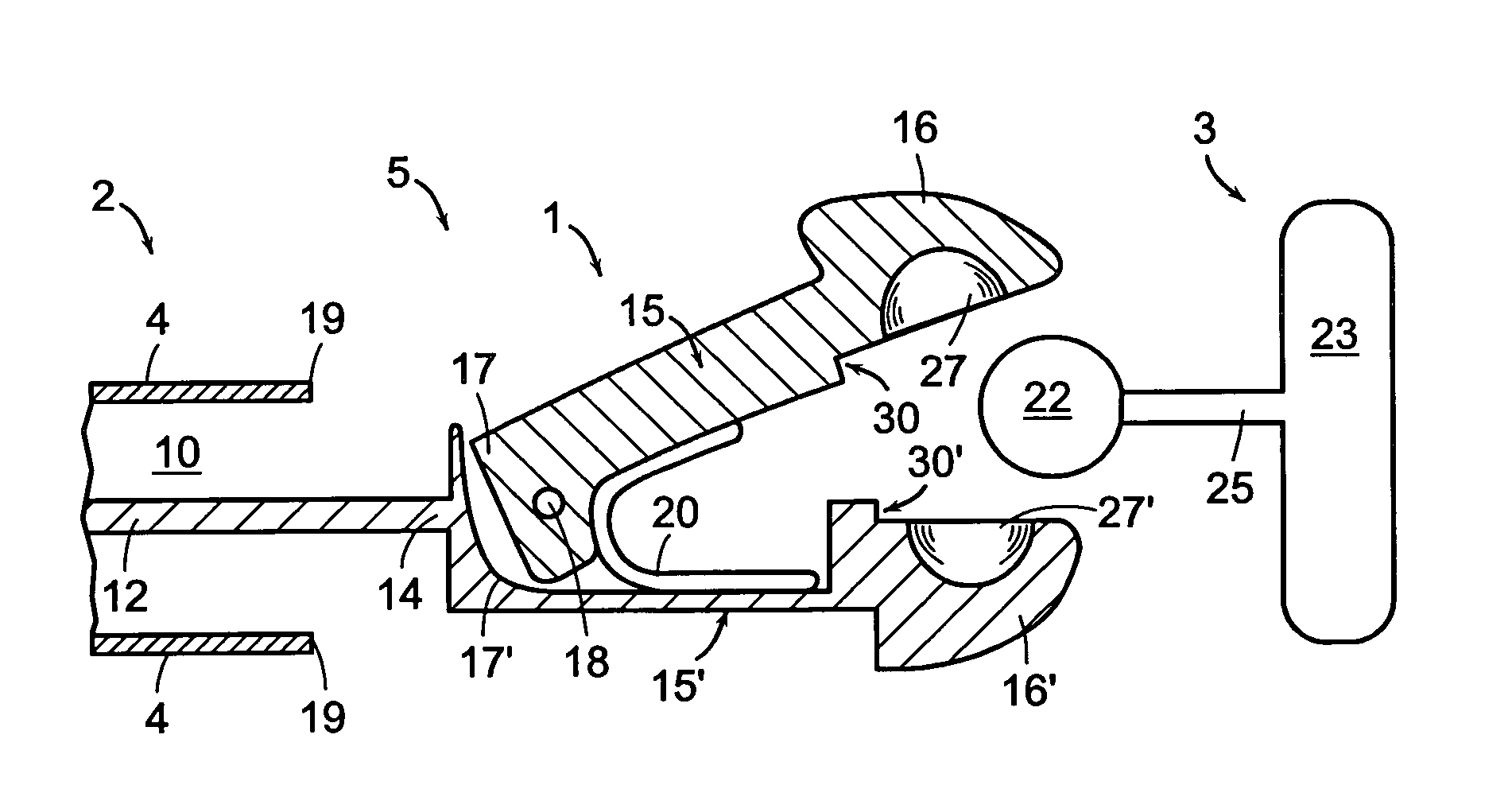
[0031]An interventional delivery system described herein includes a tubular portion, a core wire that slides in the lumen of the tubular portion, and a coupling device at the distal end of the core wire that couples to an implant.

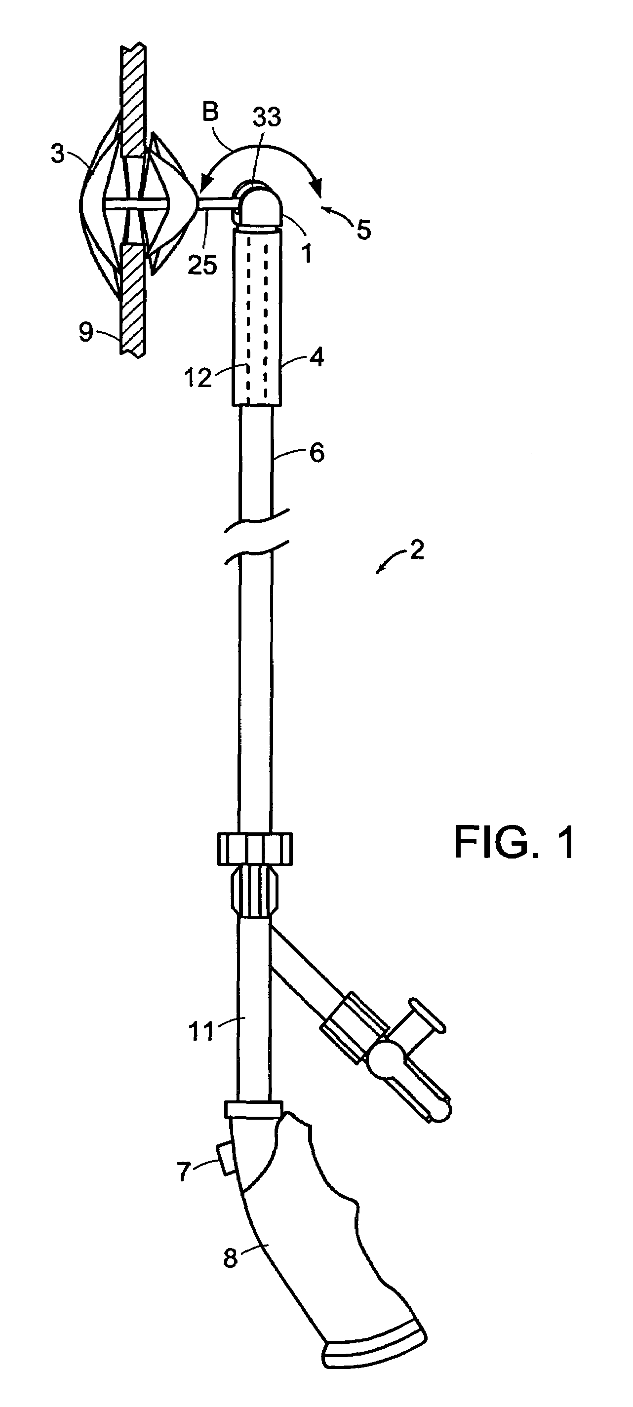
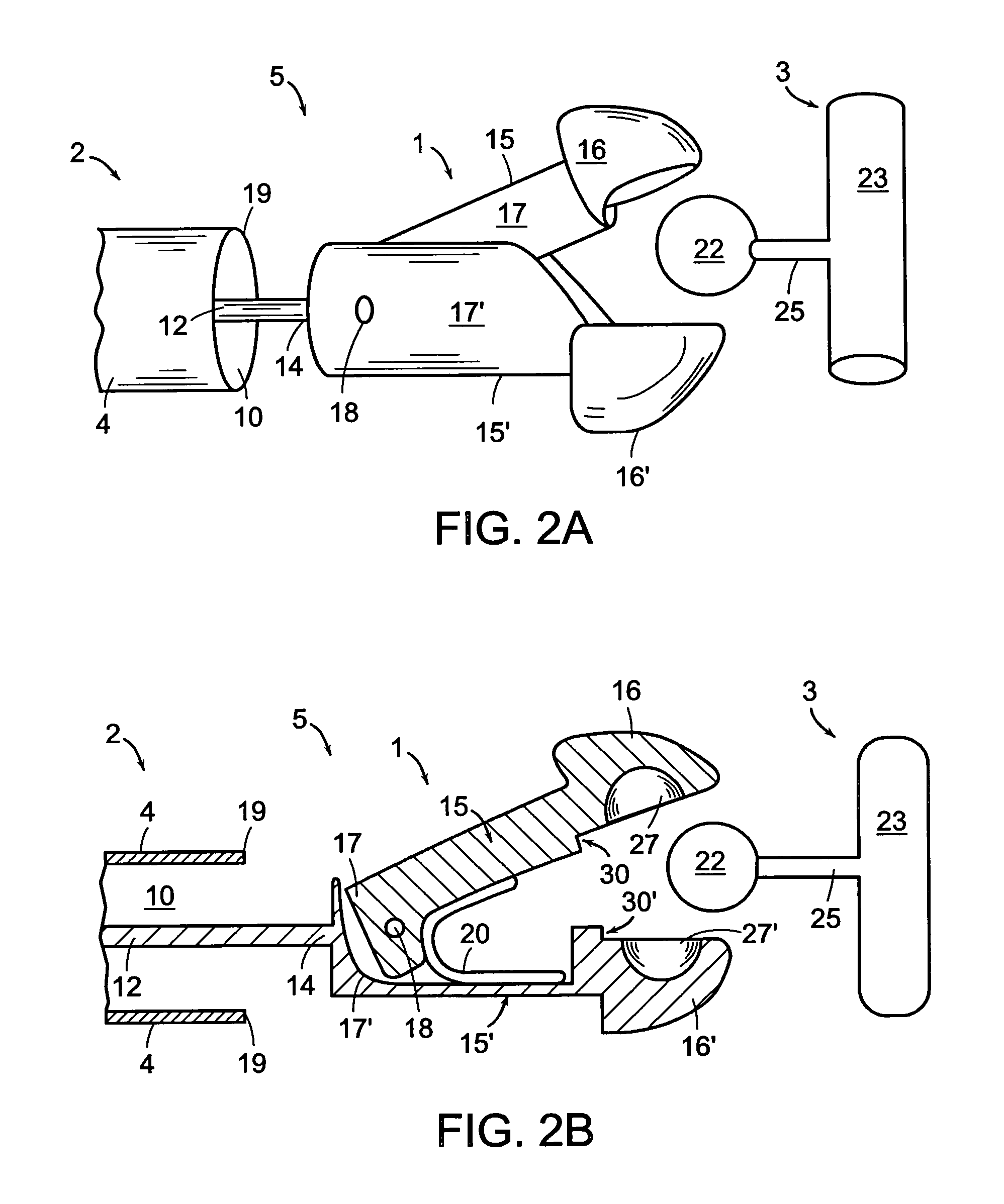
[0032]Referring to FIG. 1, in accordance with the present invention, a coupling device 1 disposed at the distal end 5 of an interventional delivery system 2 provides a mechanism for pivoting an implant 3 (e.g., a septal occluder) with respect to the coupling device 1 in order to avoid bending or twisting of the distal end 5 of the delivery system 2 during the delivery of the implant 3. In one embodiment according to the invention, the interventional delivery system 2 may include a distal sleeve 4 connected to a tubular body portion 6, which can be a catheter having a proximal end 11 connected to a handle 8. As an example, the implant 3 is shown to be a septal occluder planted in an opening in the atrial septum 9.

[0033]The term “implant” used herein includes...


PUM

PropertyMeasurementUnit
shapeaaaaaaaaaa
outer diameteraaaaaaaaaa
lengthaaaaaaaaaa

Abstract

A coupling system is disposed at the distal end of an interventional delivery system for coupling to an implant. The coupling device has a first and second prong connected at one end. The other end of the prongs open or close to release or trap an object, e.g., a bead tethered from an implant. A slot at the distal end of the coupling device allows extra degrees of flexibility for the coupling device.

Description

CROSS REFERENCE TO RELATED APPLICATIONS[0001]This application claims priority to and the benefit of U.S. provisional patent application Nos. 60 / 364,017, filed Mar. 15, 2002, and No. 60 / 382,528, filed May 21, 2002. The disclosure of the above applications are hereby incorporated by reference.TECHNICAL FIELD[0002]The invention generally involves coupling or attaching devices used in a transcatheter delivery system and their uses in connection with delivering or retrieving a medical implant.BACKGROUND OF THE INVENTION[0003]Numerous systems for percutaneous transcatheter delivery of implants have been devised over the years in order to assist physicians in delivering and positioning implants, for example, occluders, within a patient, preferably in a minimally invasive manner. A problem with many of the known delivery systems is that they can often adversely affect positioning of the device that is being implanted, which forces the doctor to estimate and take into consideration such effe...

Claims


Application Information

Patent Timeline
Patent Type & Authority Patents(United States)
IPC IPC(8): A61B17/28A61B17/42A61B17/44A61B10/00A61B10/06A61B17/00A61B17/12A61B17/22A61B19/00A61F2/00A61F2/01A61F2/02A61F2/06A61F2/84
CPCA61B17/0057A61B10/06A61B17/22031A61B2017/00004A61B2017/00243A61B2017/00575A61B2017/00606A61B2017/00623A61B2017/1205A61B2017/2937A61B2019/2242A61B2019/2249A61F2/95A61F2002/011A61F2002/30062A61F2002/30079A61F2210/0004A61F2210/009A61F2250/0067A61B34/71A61B34/72A61B2017/00477A61F2/011
Inventor OPOLSKI, STEVEN W.PEAVEY, TODD A.
Owner WL GORE & ASSOC INC
Why Eureka
Try Eureka