Phase locking on aliased frequencies

a phase locking and aliasing technology, applied in the direction of oscillator generators, pulse automatic control, electrical equipment, etc., can solve the problems of limiting the usefulness of many ate applications, reducing the open-loop gain, and increasing the error rate of loop tracking errors

Inactive Publication Date: 2008-03-18
TERADYNE
View PDF5 Cites 14 Cited by
  • Summary
  • Abstract
  • Description
  • Claims
  • Application Information

AI Technical Summary

Problems solved by technology

Nevertheless, we have recognized certain shortcomings in the PLL 100, which limits its usefulness in many ATE applications.
The speed of the VCOs in these applications often greatly exceeds the speed of the phase detectors.
As is known, reducing open-loop gain increases loop tracking errors.
It also impairs the ability of the loop to reject noise.
Frequency dividers are commonly implemented as counters, which are known to create spurious noise at their outputs.
Reducing bandwidth to this degree, however, has the effect of reducing programming speed of the PLL 100, which can negatively impact ATE system performance and throughput.

Method used


Image

  • Phase locking on aliased frequencies
  • Phase locking on aliased frequencies
  • Phase locking on aliased frequencies

Examples


Embodiment Construction

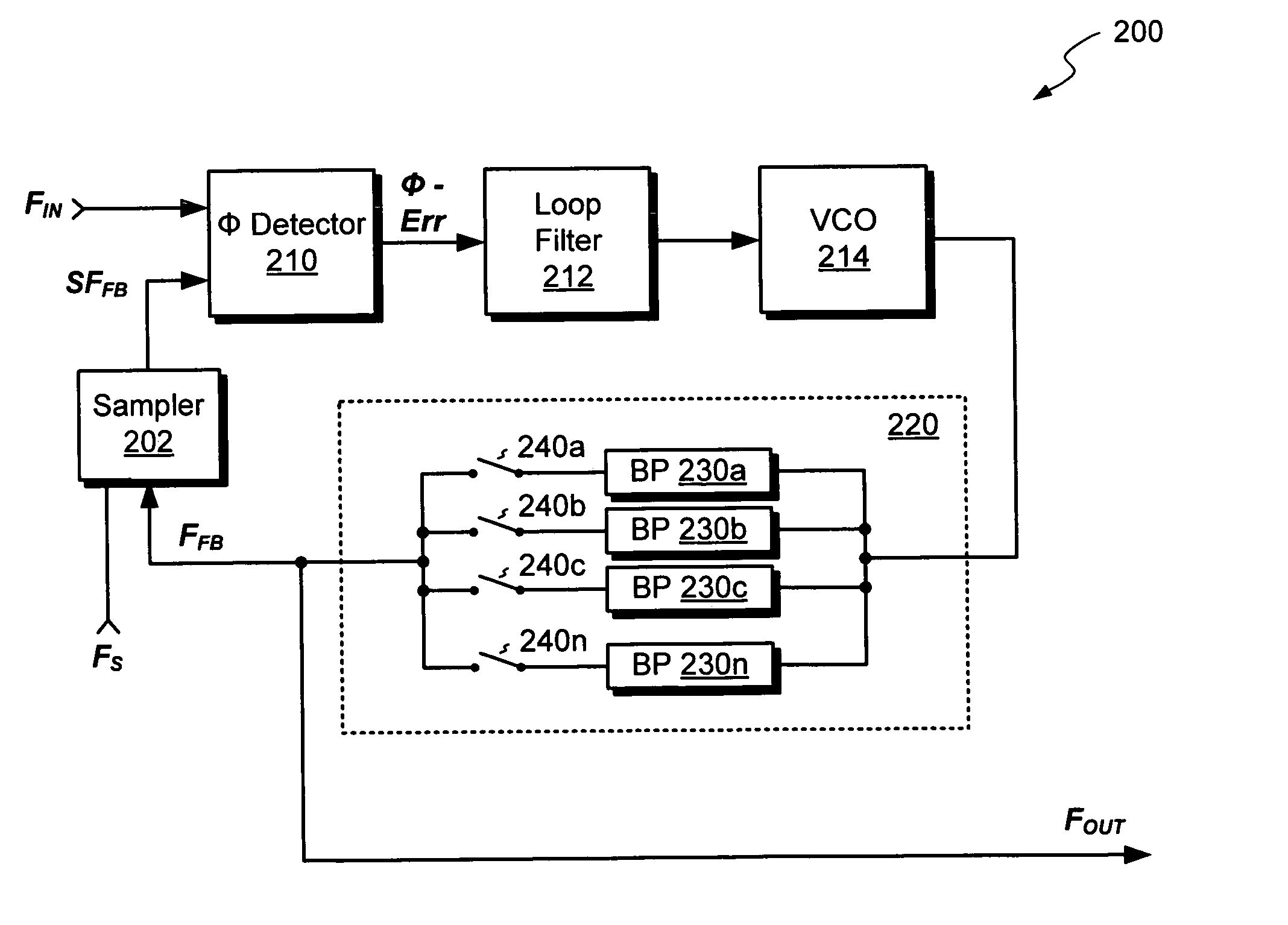
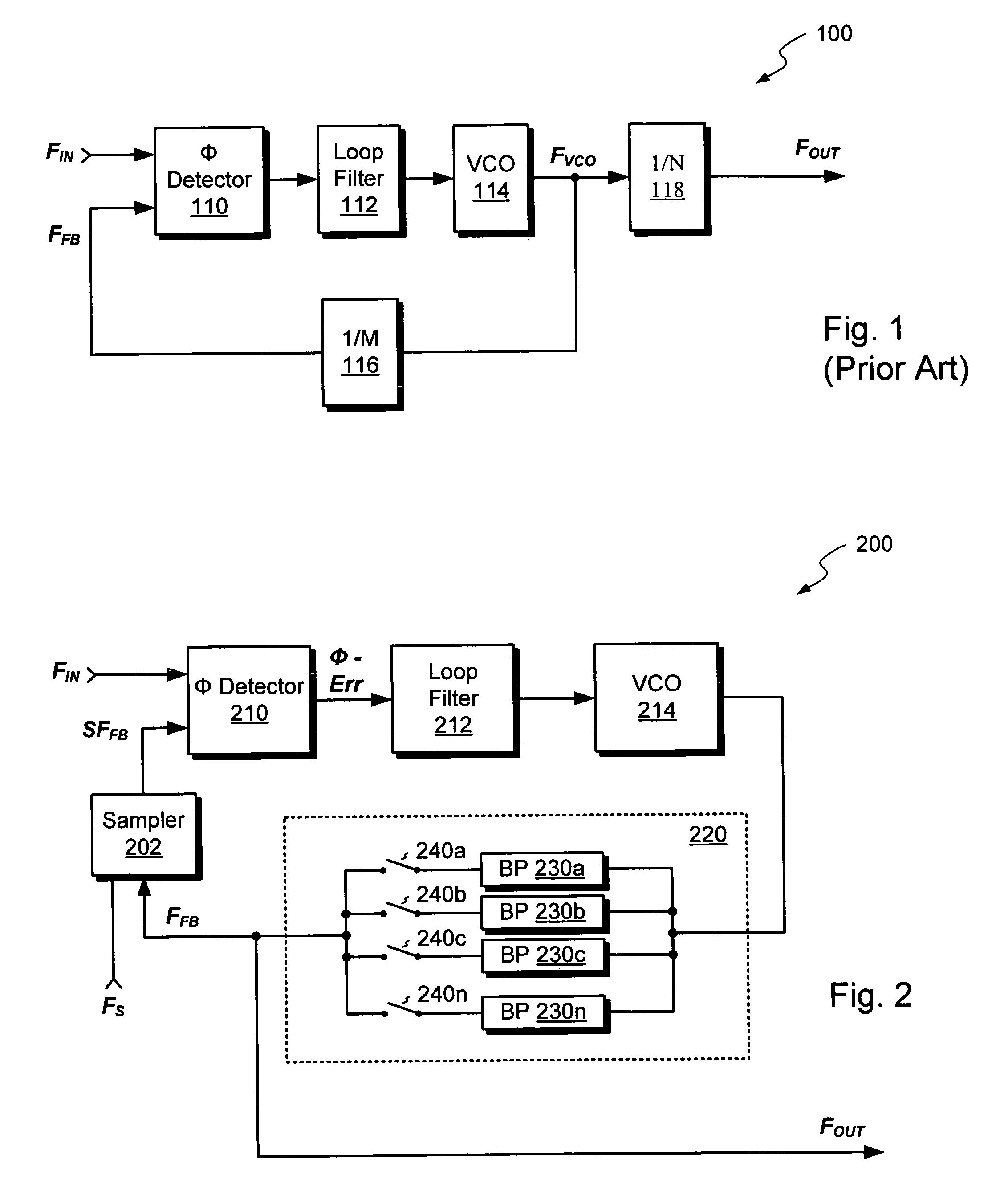
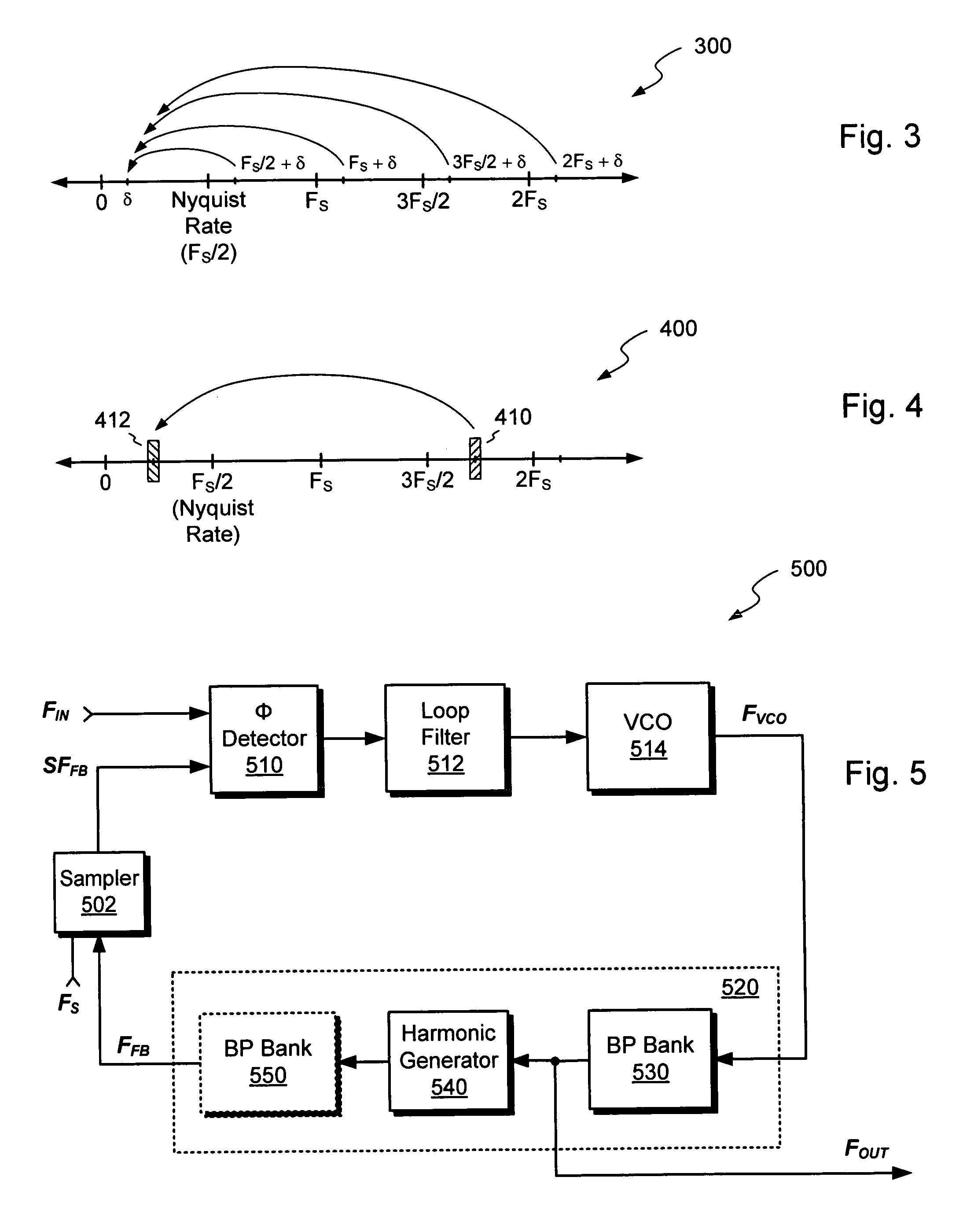
[0027]FIG. 2 shows an illustrative embodiment of a phase-locking circuit 200. The phase-locking circuit 200 receives an input signal, FIN, and produces an output signal, FOUT. The circuit 200 includes a sampler 202, a phase detector 210, a loop filter 212, and a controllable oscillator, such as a VCO (voltage-controlled oscillator) 214. The sampler 202 receives a feedback signal, FFB, at its input and provides a sampled feedback signal, SFFB, at its output. The phase detector 210 has 2 inputs and an output. The first input receives the input signal FIN, and the second input receives the sampled feedback signal, SFFB. The loop filter 212 and the VCO 214 each have an input and an output.

[0028]The circuit 200 also includes a circuit path 220, coupled from the output of the VCO 214 to the input of the sampler 202, for providing the feedback signal, FFB. Bandpass filters 230a-230n are preferably provided in the circuit path 220. These bandpass filters are preferably individually selectab...


PUM


Abstract

A phase-locked loop (200) includes a sampler (202), a phase detector (210), a loop filter (212), and a VCO (214). The loop achieves frequency multiplication without the need for a divider in the loop's feedback path. The VCO (214) is operated above the Nyquist rate of the sampler, causing the loop to lock on an aliased signal. Any variations in the VCO output frequency (i.e., jitter or phase noise) are fed back to the phase detector (210) 1-for-1, without attenuation normally associated with frequency dividers. Loop gain can therefore be kept high, even in loops that provide high closed loop frequency multiplication. According to one variation, a harmonic generator (540) is placed between the VCO and the sampler, thus causing the loop to lock on harmonics of the VCO frequency. Open loop gain and precision are thus further improved.

Description

CROSS-REFERENCES TO RELATED APPLICATIONS[0001]The following patent document is incorporated by reference herein in its entirety:[0002]U.S. patent application Ser. No. 10 / 817,780, entitled “High Performance Signal Generation,” filed Apr. 2, 2004.STATEMENT REGARDING FEDERALLY SPONSORED RESEARCH OR DEVELOPMENT[0003]Not Applicable.REFERENCE TO MICROFICHE APPENDIX[0004]Not ApplicableBACKGROUND[0005]1. Field of the Invention[0006]This invention relates generally to automatic test equipment for electronics, and, more particularly, to techniques for generating periodic signals for testing electronic devices.[0007]2. Description of the Related Art[0008]Electronics manufacturers commonly use automatic test equipment (ATE) for testing semiconductor components and electronic assemblies. ATE reduces costs to manufacturers by allowing products to be tested early in the manufacturing process. Early testing allows defective units to be identified and discarded before substantial additional costs ar...

Claims


Application Information

Patent Timeline
Patent Type & Authority Patents(United States)
IPC IPC(8): H03L7/085
CPCH03L7/20
Inventor XU, FANG
Owner TERADYNE
Why Eureka
Try Eureka