
Method and apparatus for reducing the infrared and radar signature of a vehicle

a technology of infrared and radar signature, which is applied in the direction of aircraft floors, aircraft stabilisation, silicon compounds, etc., can solve the problems of reducing the performance and the range of aircraft, affecting the aerodynamics of aircraft, and high likelihood of being targeted, so as to reduce the radar signature of aircraft, reduce the structural integrity of honeycomb structure, and reduce the radar/microwave and thermal/infrared signature of aircra

Active Publication Date: 2008-03-18
TEXTRON INNOVATIONS
View PDF12 Cites 23 Cited by
  • Summary
  • Abstract
  • Description
  • Claims
  • Application Information

AI Technical Summary

Benefits of technology

The present invention is about a new way to reduce the radar and infrared signature of a vehicle. It uses honeycomb structures with large cells sizes, which were previously thought to be too big for effective use. The invention also suggests using pre-impregnated materials, multiple layers of cores, electrically resistive sheets, fabrics, or mat plies, opacification coatings, film adhesives, low emissivity coatings, and radar attenuating materials in film adhesives. The invention can be used in military helicopters, aircraft, unmanned aerial vehicles, or ground vehicles. It allows for a lighter and more cost-effective honeycomb structure to be added to the vehicle without compromising its strength or radar attenuation properties.

Problems solved by technology

This need to avoid detection is especially critical for aircraft, such as airplanes and helicopters, which have a high likelihood of being targeted by enemy air and ground forces using any and all of the above detection methods.
Although these methods can be very effective when properly employed, each of these methods has drawbacks.
In most cases, the addition of infrared-insulative and infrared-absorptive materials to the outer skin of the aircraft represents a significant addition of weight to the aircraft and may interfere with the aerodynamics of the aircraft, reducing the performance and the range of the aircraft.
Unfortunately, additional radar-absorptive materials carry with them additional weight, and shapes optimized for minimal radar signature generally exhibit less-than ideal aerodynamic characteristics.

Method used


Image

  • Method and apparatus for reducing the infrared and radar signature of a vehicle
  • Method and apparatus for reducing the infrared and radar signature of a vehicle
  • Method and apparatus for reducing the infrared and radar signature of a vehicle

Examples


Embodiment Construction

[0021]While the making and using of various embodiments of the present invention are discussed in detail below, it should be appreciated that the present invention provides many applicable inventive concepts, which can be embodied in a wide variety of specific contexts. The specific embodiments discussed herein are merely illustrative of specific ways to make and use the invention and do not delimit the scope of the invention.

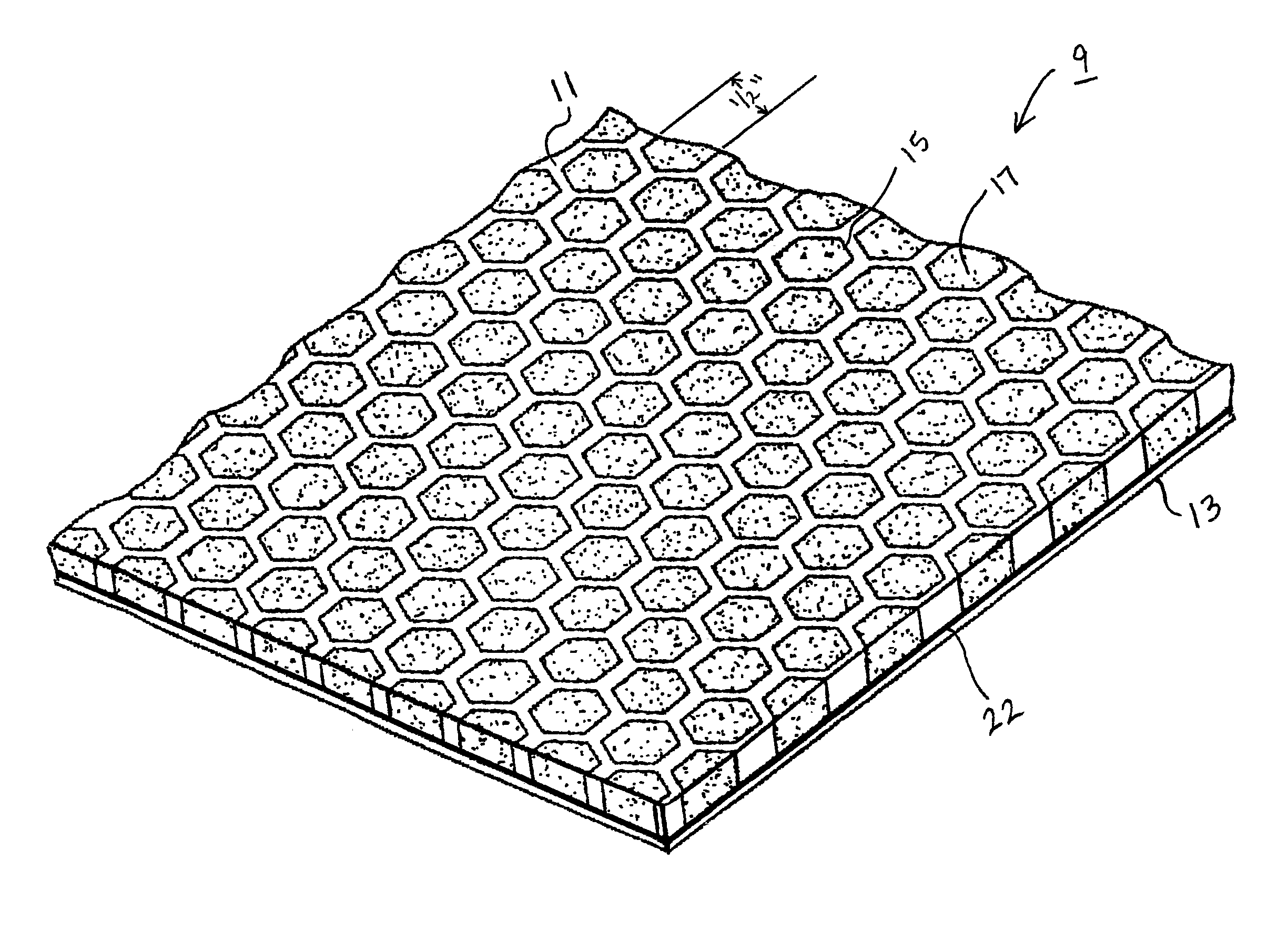
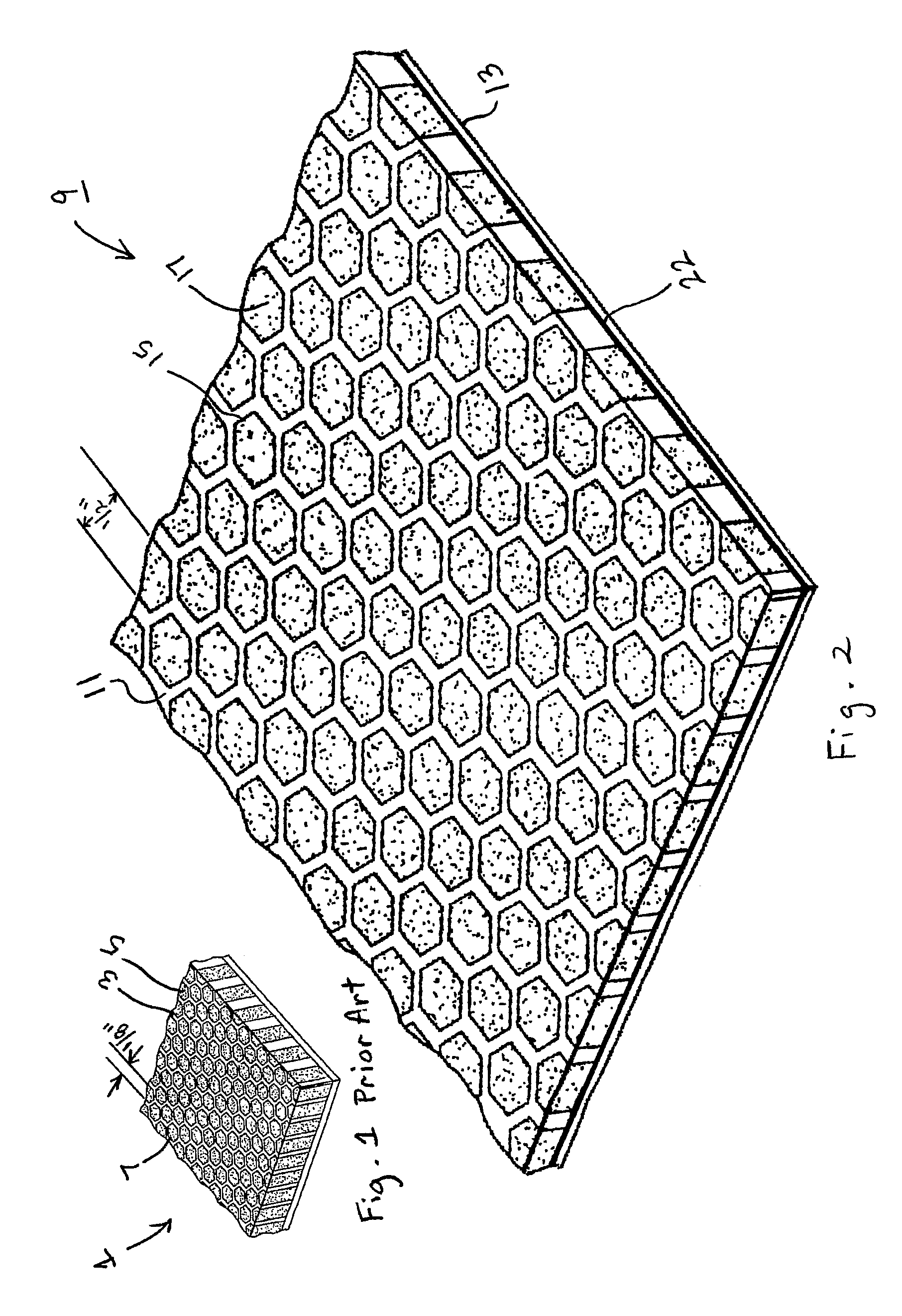
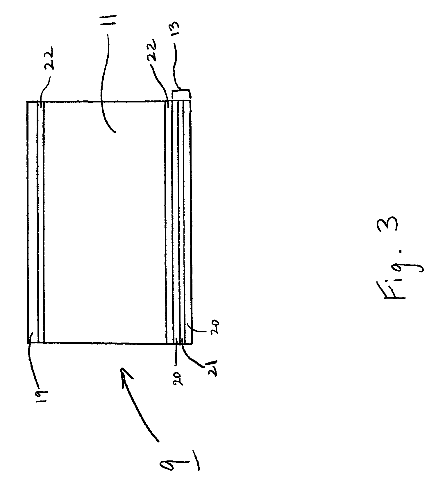
[0022]Referring now to FIGS. 2 and 3 in the drawings, a partial perspective view and a schematic representation of the preferred embodiment of a radar-absorbing panel 9 according to the present invention are illustrated, respectively. As illustrated in FIG. 2, panel 9 comprises a honeycomb core 11 and a lower skin 13 attached to the bottom of core 11. As seen in FIG. 2, core 11 comprises an array of individual cells 15 which are preferably filled with an aerogel 17. Lower skin 13 is typically constructed of a combination of discrete layers of woven fiberglass h...


PUM


Abstract

A radar-absorbing panel (9) includes a honeycomb core (11) and a lower skin (13), where the lower skin (13) is attached to the bottom of the honeycomb core (11). The honeycomb core (11) is made up of individual cells (15), which may be filled with aerogel. The individual cells (15) are approximately ½ of an inch in size with polygonal shape.

Description

[0001]The U.S. Government has a paid-up license in this invention and the right in limited circumstances to require the patent owner to license others on reasonable terms as provided for by the terms of Contract No. DAAH10-03-2-0005; Work Order 4 YHS.TECHNICAL FIELD[0002]The present invention relates generally to methods of reducing the infrared and radar signature of a vehicle, specifically to the use of insulative and absorptive materials to reduce the amount of infrared radiation being emitted, and the radar signals being reflected, from certain portions of the vehicle.DESCRIPTION OF THE PRIOR ART[0003]Vehicles involved in military operations have a need to reduce their visibility to opposing forces. This need exists for all methods modem military forces use to detect and target enemies. Examples of such methods include visual detection, audio detection, active and passive radar, and infrared detection. This need to avoid detection is especially critical for aircraft, such as air...

Claims


Application Information

Patent Timeline
Patent Type & Authority Patents(United States)
IPC IPC(8): H01Q17/00F41H3/00G01S13/00
CPCF41H3/00H01Q17/00H01Q17/008Y10S428/919
Inventor WILLIAMS, RANDY B.
Owner TEXTRON INNOVATIONS
Learn More