Connection protection mechanism for dual homed access, aggregation and customer edge devices

a protection mechanism and connection protection technology, applied in the field of data communication, can solve the problems of inability to design traffic engineered networks, devices without the capability of per connection end-to-end or local protection, and off-the-shelf conventional access devices do not have protection capabilities, etc., and achieve the effect of increasing reliability

Inactive Publication Date: 2008-03-18
NOKIA SIEMENS NETWORKS ETHERNET SOLUTIONS
View PDF4 Cites 239 Cited by
  • Summary
  • Abstract
  • Description
  • Claims
  • Application Information

AI Technical Summary

Benefits of technology

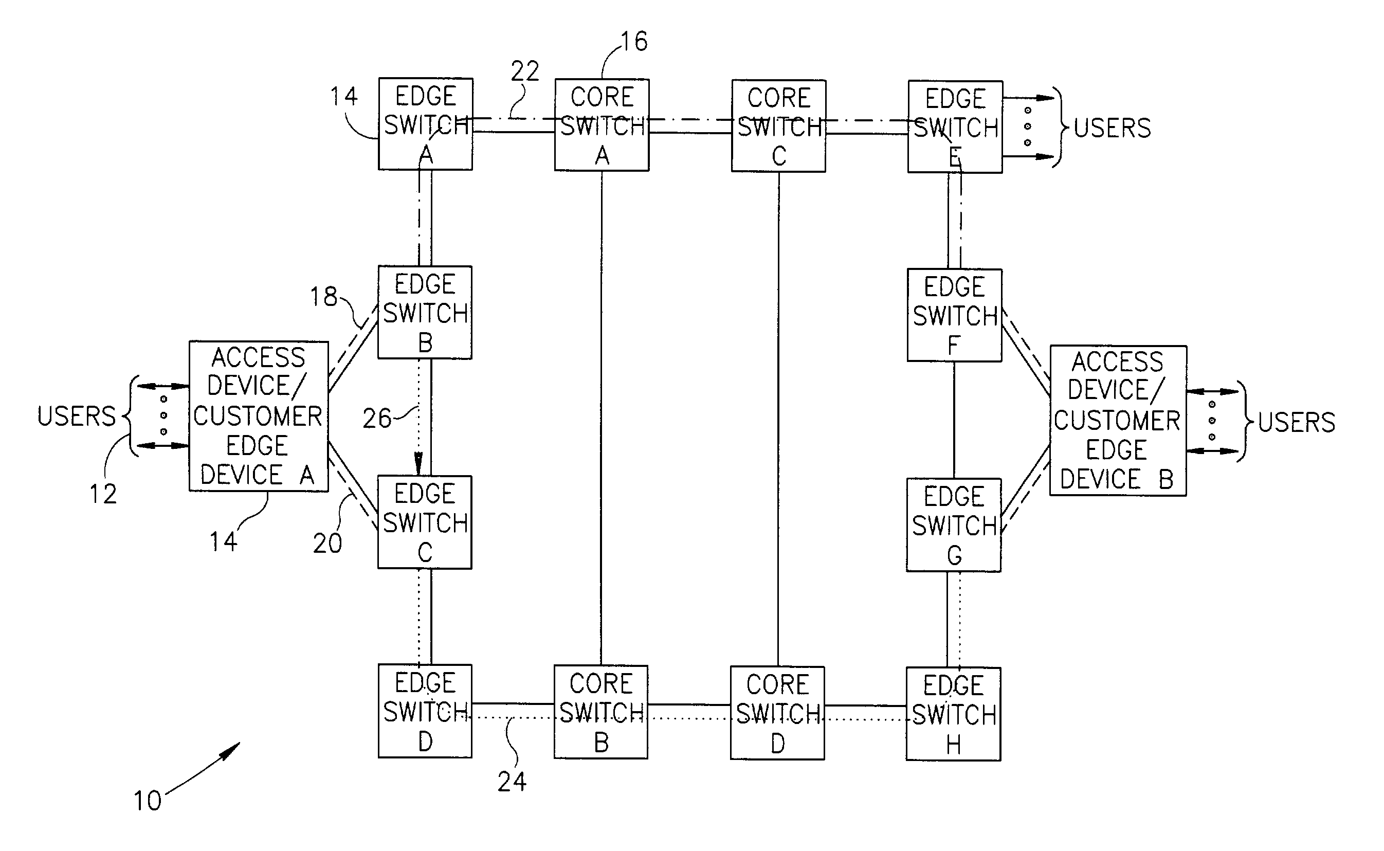
[0031]The protection mechanism of the present invention is operative to provide end-to-end and fast local protection for off the shelf access devices that do not have any per connection dual-homing protection capabilities built in. The access device is connected via two ports to two edge switches in the VLAN stack portion of the network via two separate physical uplinks. Connections are assigned to VLANs on the access device. Traffic of a specific connection normally flows over one of the uplinks absent a failure. The preferred uplink may be different for different connections, thus providing traffic load-balancing between the uplinks. In the event of a failure, the traffic is switched to the other uplink. This behavior can be achieved in the AD, for example, by setting a Link Aggregation Group (LAG) between the two uplinks, with a specific LAG function that sends all packets of a single VLAN to one of the uplinks as long as both are operational.
[0032]Separate uplinks between the access device and th

Problems solved by technology

Off the shelf conventional access devices do not have protection capabilities.
These devices have no capability for per connection end-to-end or local protection.
STP does not have a per connection notion, and creates a

Method used


Image

  • Connection protection mechanism for dual homed access, aggregation and customer edge devices
  • Connection protection mechanism for dual homed access, aggregation and customer edge devices
  • Connection protection mechanism for dual homed access, aggregation and customer edge devices

Examples


Embodiment Construction

Notation Used Throughout

[0059]The following notation is used throughout this document.

[0060]

TermDefinitionADAccess DeviceASICApplication Specific Integrated CircuitATMAsynchronous Transfer ModeCD-ROMCompact Disc-Read Only MemoryCECustomer EquipmentCPUCentral Processing UnitCR-LDPConstraint-based Label Distribution ProtocolCSCore SwitchCSIXCommon Switch InterfaceDATDigital Audio TapeDSPDigital Signal ProcessorDVDDigital Versatile DiskEEPROMElectrically Erasable Programmable Read Only MemoryEIRExcess Information RateEPROMErasable Programmable Read Only MemoryESEdge SwitchFDDIFiber Distributed Data InterfaceFEFast EthernetFPGAField Programmable Gate ArrayGEGigabit EthernetIETFInternet Engineering Task ForceIPInternet ProtocolISISIntermediate System to Intermediate SystemITUInternational Telecommunications UnionLACPLink Aggregation Control ProtocolLAGLink Aggregation GroupLANLocal Area NetworkLSBLeast Significant BitLSPLabel Switched PathLSRLabel Switching RouterMACMedia Access ControlM...


PUM


Abstract

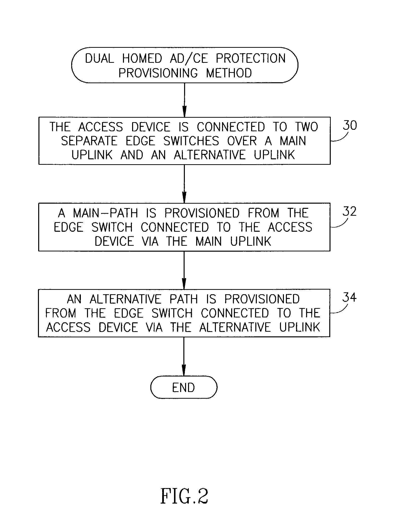
A protection mechanism capable of providing both local and end-to-end connection protection for dual homed access/aggregation devices or customer-edge devices in a network. The protection mechanism provides end-to-end and fast local protection for off the shelf access devices that do not have any built in per-connection protection capabilities. The access device is connected via two separate physical uplinks to two edge switches of the network. For each connection to be protected, a main path is provisioned from one edge switch and an alternative path is provisioned from the other edge switch. The edge switches are adapted to comprise means for switching traffic from the main path to the alternative path in the event a failure along the main path is detected. Failures both in the stack portion, the core portion and in the access device uplinks are protected against.

Description

REFERENCE TO RELATED APPLICATIONS[0001]This application is related to U.S. application Ser. No. 10 / 190,236, filed Jul. 5, 2002, entitled “End-to-End Notification of Local Protection Using OAM Protocol,” now U.S. Pat. No. 7,197,008 and to U.S. application Ser. No. 10 / 201,852, filed Jul. 23, 2002, entitled “Fast Connection Protection In A Virtual Local Area Network Based Stack Environment”, now U.S. Pat. No. 7,093,027, both similarly assigned and incorporated herein by reference in their entirety.FIELD OF THE INVENTION[0002]The present invention relates generally to data communications and more particularly relates to a mechanism for providing end-to-end and fast local connection protection for dual homed access, aggregation and client-edge devices.BACKGROUND OF THE INVENTION[0003]Currently, the number of data networks and the volume of traffic these networks carry are increasing at an ever increasing rate. The network devices making up these networks generally consist of specialized ...

Claims


Application Information

Patent Timeline
IPC IPC(8): H04L12/56
CPCH04L12/2863H04L12/462H04L45/04H04L45/22H04L45/28Y02B60/33Y02D30/50
Inventor SHABTAY, LIORRAZ, YARON
Owner NOKIA SIEMENS NETWORKS ETHERNET SOLUTIONS
Why Eureka
Try Eureka