Measuring strain in a structure using a sensor having an electromagnetic resonator

a technology of electromagnetic resonance and sensor, applied in the direction of electrical/magnetic means, structural/machine measurement, electrical/magnetic deterioration and increasing structural deficiencies, etc., can cause corrosion and compromise the integrity of monitoring systems, fiber-optic units can be difficult to install, and can be subject to temperature dri

Inactive Publication Date: 2008-03-25
SMART AUTONOMOUS SOLUTIONS
View PDF33 Cites 18 Cited by
  • Summary
  • Abstract
  • Description
  • Claims
  • Application Information

AI Technical Summary

Problems solved by technology

The increased weight and numbers of today's trucks compared with design loads that were used for the roads and bridges at the time of construction, combined with aging, environmental conditions and the use of corrosive salts has resulted in deterioration and increasing structural deficiencies.
Over time these wires can corrode and compromise the integrity of the monitoring system.
In addition, fiber-optic units can be difficult to install and can be subject to temperature drift.
Furthermore, when the connections linking these sensor systems break then the monitoring system will not function.

Method used


Image

  • Measuring strain in a structure using a sensor having an electromagnetic resonator
  • Measuring strain in a structure using a sensor having an electromagnetic resonator
  • Measuring strain in a structure using a sensor having an electromagnetic resonator

Examples


Embodiment Construction

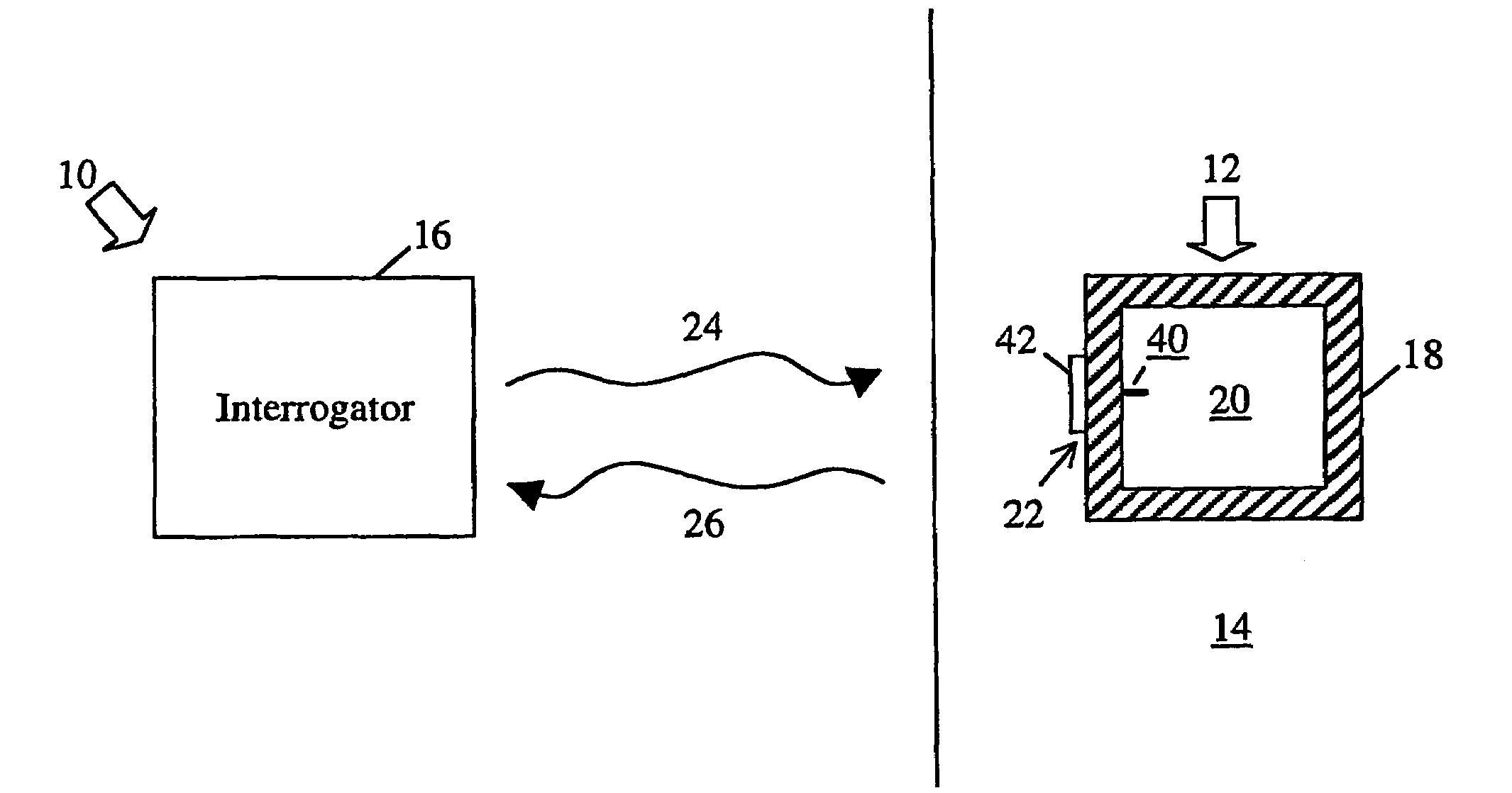
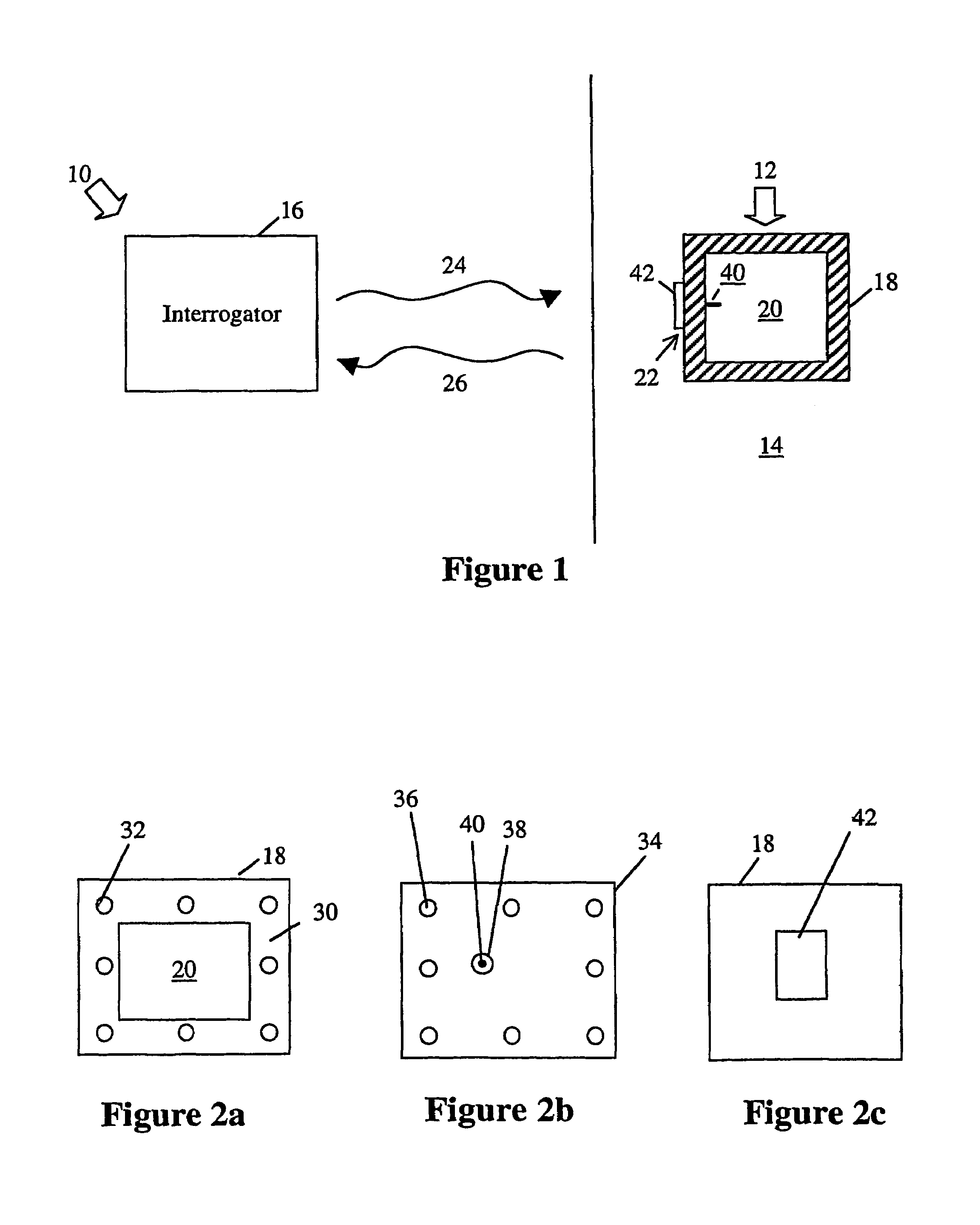
[0036]Referring now to FIG. 1, shown therein is a partial cross-sectional front view of a sensor system 10 for determining strain 12 experienced by a structure 14. The sensor system 10 comprises an interrogator 16 and a plurality of sensors 18. The structure 14 could be for example, but not limited to, a bridge, a road, an overpass, a building, an aircraft or the like and the strain 12 may result from for example, but not limited to, force, temperature, or the like. The integrity of the structure 14 could be monitored at any given time to indicate when repair or replacement is necessary for the structure 14. To achieve this, several sensors 18 would be strategically placed at various locations of the structure 14 that are susceptible to strain (these locations are known to those skilled in the art). For simplicity of illustration and explanation only one sensor 18 and only a partial view of the structure 14 is shown in FIG. 1. The sensors 18 do not require a source of power and coul...


PUM

PropertyMeasurementUnit
speedaaaaaaaaaa
frequencyaaaaaaaaaa
frequencyaaaaaaaaaa

Abstract

The system (10) comprises a sensor (18) 90×90×90×30 mm as an electromagnetic microwave cavity (20) with a coupler (22) with a wire (40) and an antenna (42). Cavity (20) produces a response signal (26) in response to an interrogation signal (24) from interrogator (16). Sensor (18) is coupled to a structure (14) to allow a strain to alter the resonance properties. 3.6 GHz is used with a detection of a 2.5 kHz change. If not temperature via strain is detected a mechanical amplifier is used with cavity (20) for temperature compensation. Continuous or intermittent narrowband signals are used as interrogation signals (24). Used with bridges for structural health monitoring. Also for aircrafts, dams, buildings, vehicles.

Description

FIELD OF THE INVENTION[0001]The present invention is related to a system and method for measuring strain that is experienced by structures. More particularly, the present invention is directed towards a wireless sensor system and method for measuring strain in structures based on electromagnetic resonance.BACKGROUND OF THE INVENTION[0002]In the 1930's the U.S. and Canadian governments began public work programs to develop a transportation infrastructure comprising roadways and bridges. The increased weight and numbers of today's trucks compared with design loads that were used for the roads and bridges at the time of construction, combined with aging, environmental conditions and the use of corrosive salts has resulted in deterioration and increasing structural deficiencies. Currently, the U.S. has 542,000 bridges that consume billions of dollars each year in construction, rehabilitation and maintenance. In Canada, there are an estimated 10,000 railroad bridges and 30,000 automobile...

Claims


Application Information

Patent Timeline
Patent Type & Authority Patents(United States)
IPC IPC(8): G01B7/16G01L1/00E01D19/00G01D5/48G01L1/14G01L1/25G01M5/00
CPCE01D19/00G01D21/00G01L1/14G01L1/255G01M5/0033G01M5/0041G01M5/0091
Inventor THOMSON, DOUGLAS JOHNBRIDGES, GREGORY E.
Owner SMART AUTONOMOUS SOLUTIONS
Why Eureka
Try Eureka