Dental bur

a technology of dentin burst and dental post, applied in the field of dental burs, can solve the problems of composite posts breaking, metal posts being difficult to remove, damaged dentin material located laterally relative to metal posts, etc., and achieve the effect of accurate and simple removal of composite materials and accurate removal of dental posts

Inactive Publication Date: 2008-03-25
MTI PRECISION PROD
View PDF6 Cites 6 Cited by
  • Summary
  • Abstract
  • Description
  • Claims
  • Application Information

AI Technical Summary

Benefits of technology

[0016]It is therefore an object of the present invention to provide a dental bur structure which accurately and simply removes composite material forming a broken composite post in order to extract the same from a tooth canal.
[0017]Another object of the present invention is to provide a dental bur structure which includes a heat-generating tip that serves as a guide for the dental bur as it travels down the tooth canal to allow accurate removal of the dental post.
[0018]A further object of the present invention is to provide a dental bur structure which is capable of removing a broken composite post without damaging adjacent dentin material.
[0019]Yet another object of the present invention is to provide a dental bur structure which is adaptable to use in a dental practitioner's existing equipment.
[0020]A further object of the present invention is to provide a dental bur structure which is useable in removing sealing materials associated with the installation of a dental post without damaging the dentin at the periphery of the root canal.
[0021]A further object of the present invention is to provide a dental bur structure which self guides its movement by removing packing material and plastic cores associated with the same.

Problems solved by technology

However, it has been found that metal posts are difficult to remove when a failure or fracture of the post occurs.
Removal techniques have often damaged dentin material located laterally relative to the metal posts.
However, despite these advantages, composite posts also break requiring removal of the same from the tooth canal.
It has been found that the ultrasonic file is very difficult to control and often drifts into the surrounding dentin tooth structure causing damage thereto.
Likewise, a hollow end cutting drill, much like a hole saw, used to remove metal posts adequately functions to remove metal posts, but tends to drift laterally when used to remove composite posts, again causing damage to the surrounding dentin material.
In the past removal devices have damaged the dentin at the peripheral portion of the canal when gutta percha and Vectra materials were partially removed to provide a space for metal or fiber posts.

Method used


Image

  • Dental bur
  • Dental bur
  • Dental bur

Examples


Embodiment Construction

[0038]Various aspects of the present invention will evolve from the following detailed description of the preferred embodiments thereof which should be taken in conjunction with the prior described drawings.

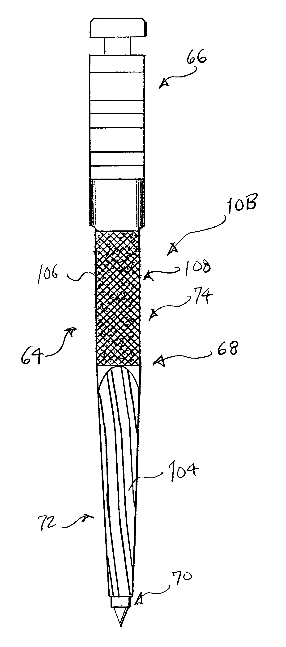
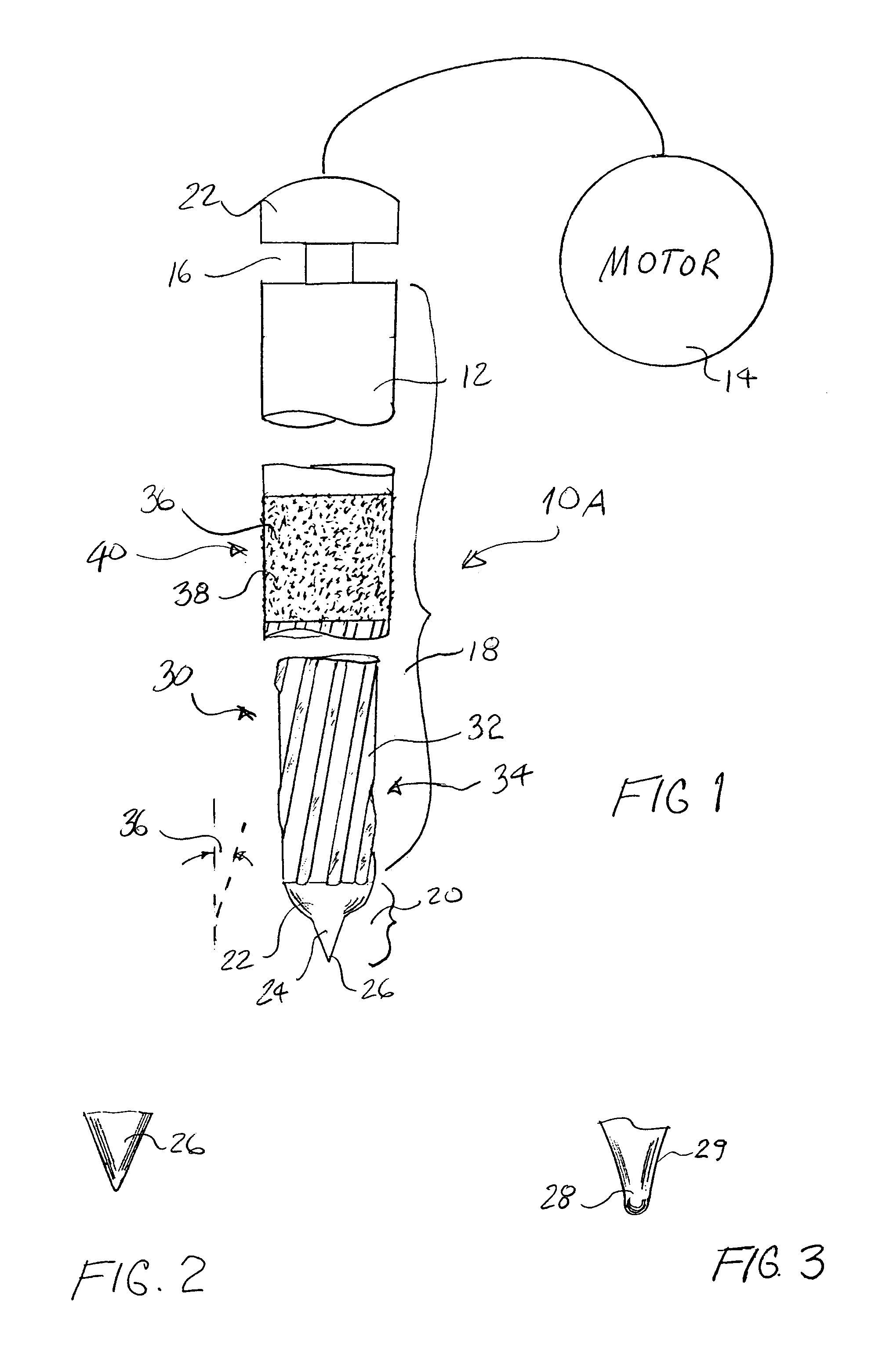
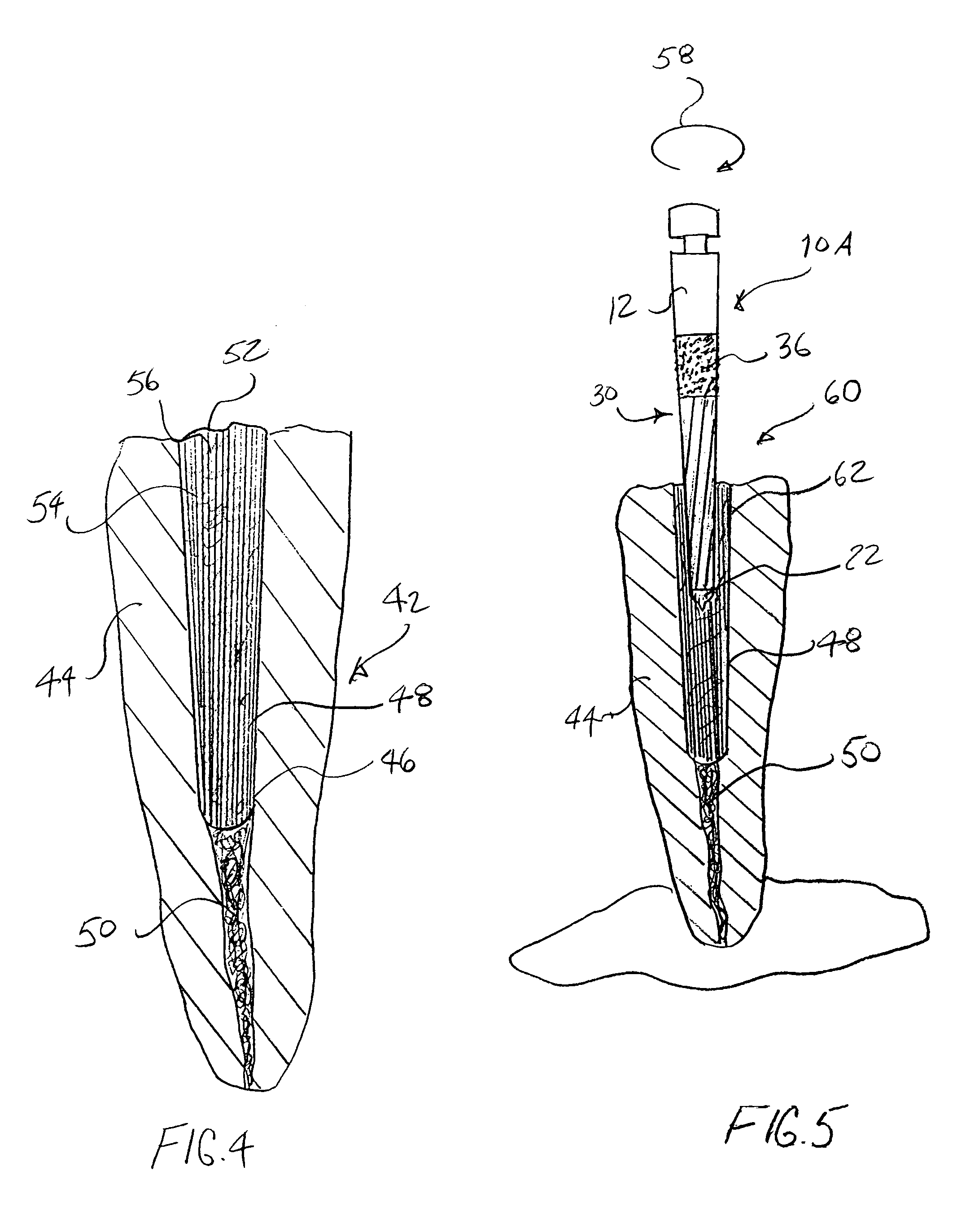
[0039]The invention as a whole is shown in the drawings by reference character 10, FIG. 1 followed by an upper case letter to denote embodiments thereof. Dental bur 10A includes as one of its elements a rotatable shaft 12 which is connected to a conventional hand piece (not shown) and rotated by a motor 14. Typically, motor 14 rotates shaft 12 at about 40,000 RPMs. Shaft 12 includes recesses 16 which are of a conventional configuration to lock into existing sources of rotation found in a dental practitioner's facility. Rotatable shaft 12 may be formed of any suitable material such as carbon steel. Rotatable shaft 12 includes a proximal portion 18 and a distal portion 20 relative to engagement end 22 which eventually links to motor 14.

[0040]Bur 10A includes as one of its elements ...


PUM


Abstract

A dental bur structure including a rotatable shaft turned by a motor. The shaft possesses a proximal portion having a fluted surface. The bur also possesses a distal portion with a smooth surface tip which generates heat to melt a composite post matrix upon activation of the shaft. The fluted surface removes a composite material while the smooth tip serves as a guide for the bur.

Description

CROSS-REFERENCES TO RELATED APPLICATIONS[0001]The present application is a continuation-in-part of U.S. patent application Ser. No. 10 / 274,568, filed 18 Oct. 2002 now U.S. Pat. No. 6,902,400, which claims the benefit of Provisional Application No. 60 / 431,146, filed 5 Dec. 2002.BACKGROUND OF THE INVENTION[0002]The present invention relates to a novel and useful dental bur which is particularly useful in removing composite dental posts and other dental material from dental canals.[0003]Dental core and post reconstitution of non-vital teeth requires the use of a root canal post. In the past, metallic posts have been used with some success. However, it has been found that metal posts are difficult to remove when a failure or fracture of the post occurs. Removal techniques have often damaged dentin material located laterally relative to the metal posts.[0004]Recently, carbon and quartz fiber-based composite posts have been available to dental practitioners as a substitute for the traditi...

Claims


Application Information

Patent Timeline
Patent Type & Authority Patents(United States)
IPC IPC(8): A61C3/02A61C5/02A61C13/30
CPCA61C3/02A61C5/023A61C5/026A61C13/30A61C5/42A61C5/46
Inventor ROETZER, PATRICK L.FELDMAN, MICHAEL
Owner MTI PRECISION PROD
Why Eureka
Try Eureka