Water particle manipulation

a technology of water particle and water particle, applied in the field of computer graphics, can solve the problems of difficult animate, water and other fluids, and not look like fluids, and achieve the effect of reducing the computational burden required

Active Publication Date: 2008-03-25
PIXAR ANIMATION
View PDF4 Cites 15 Cited by
  • Summary
  • Abstract
  • Description
  • Claims
  • Application Information

AI Technical Summary

Benefits of technology

[0007]An embodiment of the invention creates realistic sprays for simulated fluids by adding a set of spray particles to a boundary region just below the fluid surface. The set of spray particles inherit an initial state, for example a velocity, from the fluid simulation. Subsequent motion of the spray particles is determined according to a ballistic simulation, rather than a fluid simulation, thereby substantially reducing the computational burden required to animate the fluid. Spray particles that sink below a specified depth from the fluid surface are removed.

Problems solved by technology

Realistically animating water and other fluids presents a particular challenge.
The behavior of a fluid, for example a churning ocean, has a number of different characteristics that are difficult to animate by hand.
Although the set of particles animated by a typical simulation technique move, as a whole, like a fluid, it often does not look like a fluid if rendered directly.
Some rendering techniques render particles as metaballs, which are “blobs” that stretch or deform themselves into a continuous “goo.” However, metaballs give the surface of the fluid a lumpy appearance, similar to rice pudding, which is unacceptable for representing fluids such as water.
The isosurface creates a smooth, spatially-continuous fluid surface; however, this surface is temporally discontinuous due to frame-to-frame noise.
As a results, the motion of the isosurface appears jerky and discontinuous.
Although level-sets provide a smooth-looking fluid, the relatively small number of particles used for the simulation does not allow for the fluid to form “sprays” as waves break or recede.
Increasing the number of particles in the fluid simulation may allow for a more realistic spray; however, this greatly increases the computational burden of the simulation.
Additionally, the use of additional simulation particles is wasteful, as the majority of particles, such as those below the fluid surface, do not form sprays.

Method used


Image

  • Water particle manipulation
  • Water particle manipulation
  • Water particle manipulation

Examples


Embodiment Construction

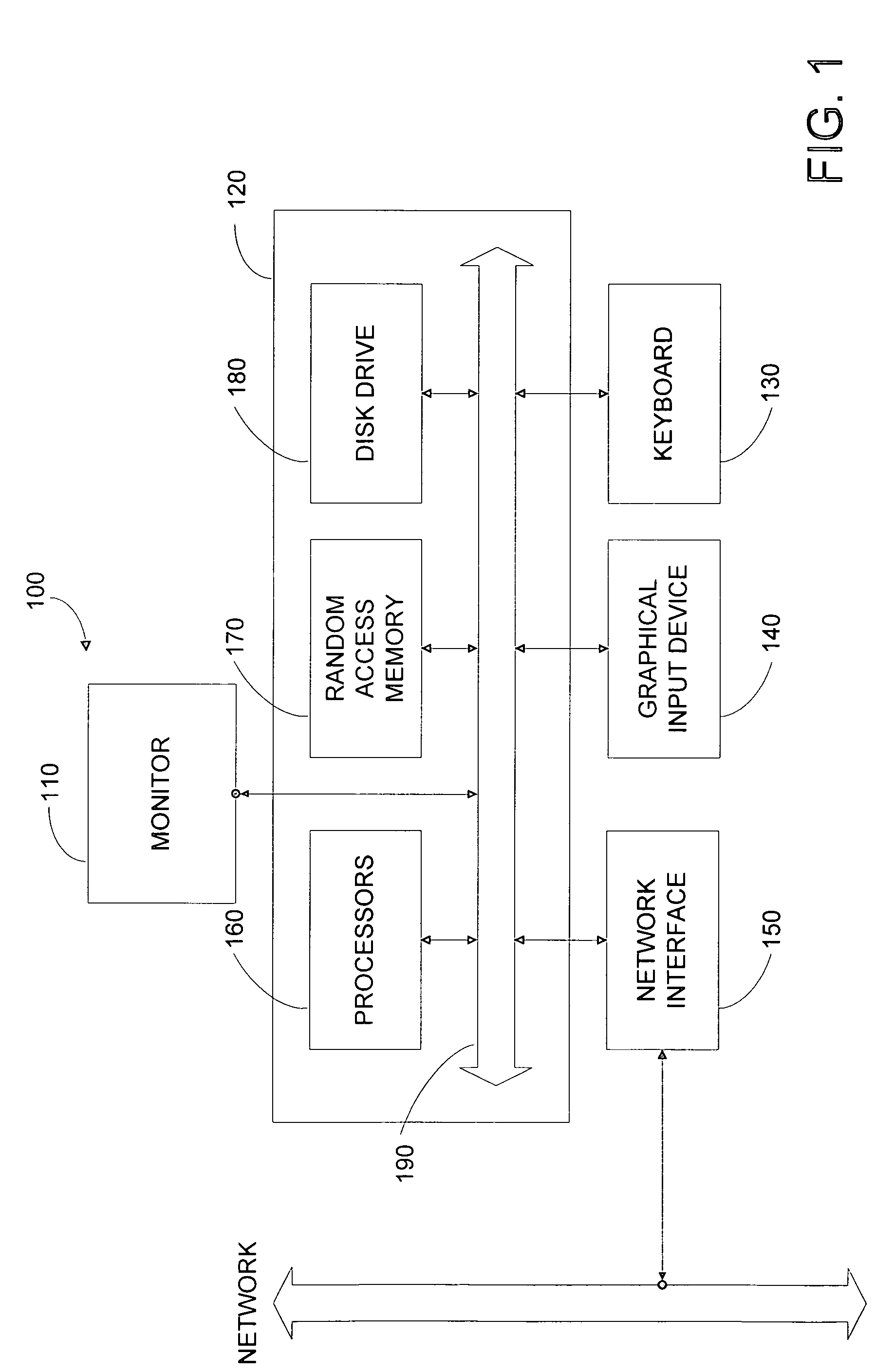
[0016]FIG. 1 illustrates an example computer system 100 capable of implementing an embodiment of the invention. Computer system 100 typically includes a monitor 110, computer 120, a keyboard 130, a user input device 140, and a network interface 150. User input device 140 includes a computer mouse, a trackball, a track pad, graphics tablet, touch screen, and / or other wired or wireless input devices that allow a user to create or select graphics, objects, icons, and / or text appearing on the monitor 110. Embodiments of network interface 150 typically provides wired or wireless communication with an electronic communications network, such as a local area network, a wide area network, for example the Internet, and / or virtual networks, for example a virtual private network (VPN).

[0017]Computer 120 typically includes components such as one or more general purpose processors 160, and memory storage devices, such as a random access memory (RAM) 170, disk drives 180, and system bus 190 interc...


PUM


Abstract

Realistic sprays for simulated fluids are created by adding a set of spray particles to a boundary region just below the fluid surface. The fluid surface is determined by solving a level set equation for a zero level corresponding to the fluid surface. Additionally, the boundary region is determined by solving the level set equation for a non-zero level corresponding to a surface at the specified depth from the fluid surface. The set of spray particles inherit an initial state, for example a velocity, from the fluid simulation. Subsequent motion of the spray particles is determined according to a ballistic simulation, rather than a fluid simulation, thereby substantially reducing the computational burden required to animate the fluid. Spray particles that sink below a specified depth from the fluid surface are removed.

Description

BACKGROUND OF THE INVENTION[0001]The present invention relates to the field of computer graphics, and in particular to methods and apparatus for realistically animating water and other fluids. The present invention relates to the field of computer graphics. Many computer graphic images are created by mathematically modeling the interaction of light with a three dimensional scene from a given viewpoint. This process, called rendering, generates a two-dimensional image of the scene from the given viewpoint, and is analogous to taking a photograph of a real-world scene. Animated sequences can be created by rendering a sequence of images of a scene as the scene is gradually changed over time. A great deal of effort has been devoted to making realistic looking rendered images and animations.[0002]Realistically animating water and other fluids presents a particular challenge. The behavior of a fluid, for example a churning ocean, has a number of different characteristics that are difficul...

Claims


Application Information

Patent Timeline
Patent Type & Authority Patents(United States)
IPC IPC(8): G06G7/50G06F17/50G06G7/48
CPCG06F17/5009G06F2217/16G06F30/20G06F2111/10
Inventor ANDERSON, JOHN
Owner PIXAR ANIMATION
Why Eureka
Try Eureka