Stationary vehicle air conditioning system

a technology for cooling systems and stationary vehicles, applied in compression machines with several condensers, light and heating apparatuses, transportation and packaging, etc., can solve the problems of cooling systems that typically require undesirable charging time, components that do not permit the cooling system to operate in an optimal manner, etc., and achieve the effect of optimizing cooling performan

Active Publication Date: 2008-04-01
BEHR GMBH & CO KG
View PDF30 Cites 42 Cited by
  • Summary
  • Abstract
  • Description
  • Claims
  • Application Information

AI Technical Summary

Benefits of technology

[0006]In a preferred embodiment of the invention, the second condenser may be connected in series or in parallel to the first condenser. The second condenser can be arranged in such a manner that is it constantly present in the refrigerant circuit, or, in the alternative, an appropriate arrangement of valves may selectively place or switch the second condenser into a series arrangement with the first condenser when the engine is not running. The provision of a second condenser connected in series with the first condenser permits an improved design of the two condensers for operation when the vehicle is operating in one of two modes, i.e., the engine is stopped or running. The first condenser with associated fan is designed, for instance, for normal operation with the engine running, and the second condenser with associated fan is designed, for instance, for stationary operation with the engine stopped, thereby permitting optimization of performance.
[0011]In place of a mechanically driven fan at the first condenser, an electrically driven one can be provided, so that a control of fan power independent of the engine is possible, whereby the cooing performance can be optimized. Alternatively, an electrically drivable fan can also be provided in addition to the mechanical fan.

Problems solved by technology

This arrangement of components does not permit the systems to operate in an optimal manner.
Other types of stationary air conditioning systems with a cold storage unit are also known in the art, but such cooling systems typically require an undesirable charging time.

Method used


Image

  • Stationary vehicle air conditioning system
  • Stationary vehicle air conditioning system
  • Stationary vehicle air conditioning system

Examples


first embodiment

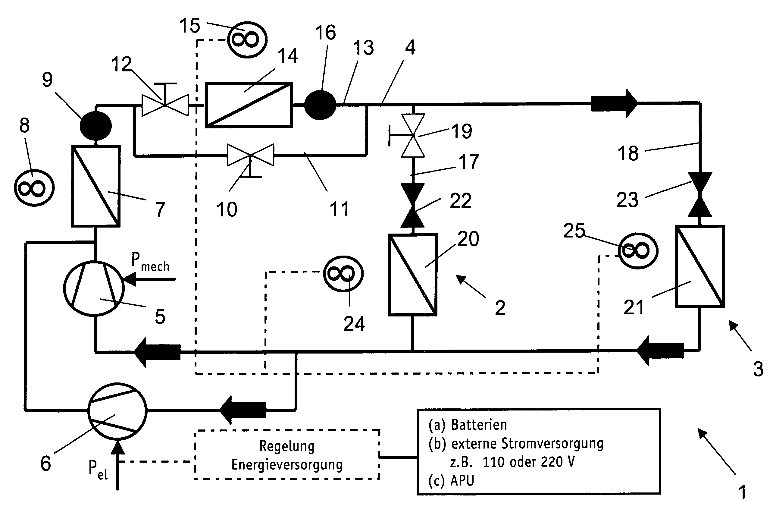
[0027]In the invention, as illustrated in FIG. 1, two compressors 5 and 6 are arranged in parallel branches of refrigerant circuit 4. In order to prevent backflow when second compressor 6 is not running, a check valve (not shown) is arranged in the corresponding branch of refrigerant circuit 4, downstream of second compressor 6 in the direction of refrigerant flow. A matching check valve can also be provided in the other branch downstream of first compressor 5.

[0028]The flow of refrigerant through circuit 4 in “normal” operation, i.e., with the vehicle's engine running, will be described first. Compressor 5 drives refrigerant, which is hot as a result of compression, through a first condenser 7 that is cooled by air via a first vehicle-engine driven fan 8. Condenser 7 may be further cooled by wind or by an air stream generated through the motion of the vehicle. Downstream of condenser 7, a first receiver 9 is arranged to collect and temporarily store excess liquid refrigerant. Downs...

second embodiment

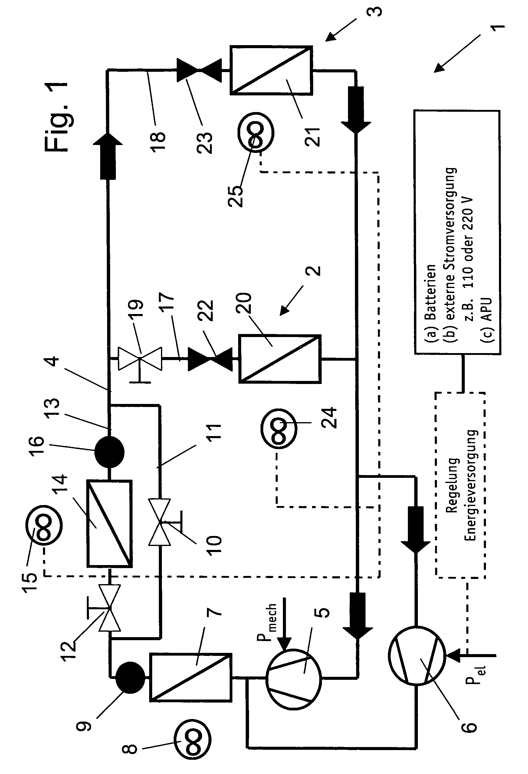
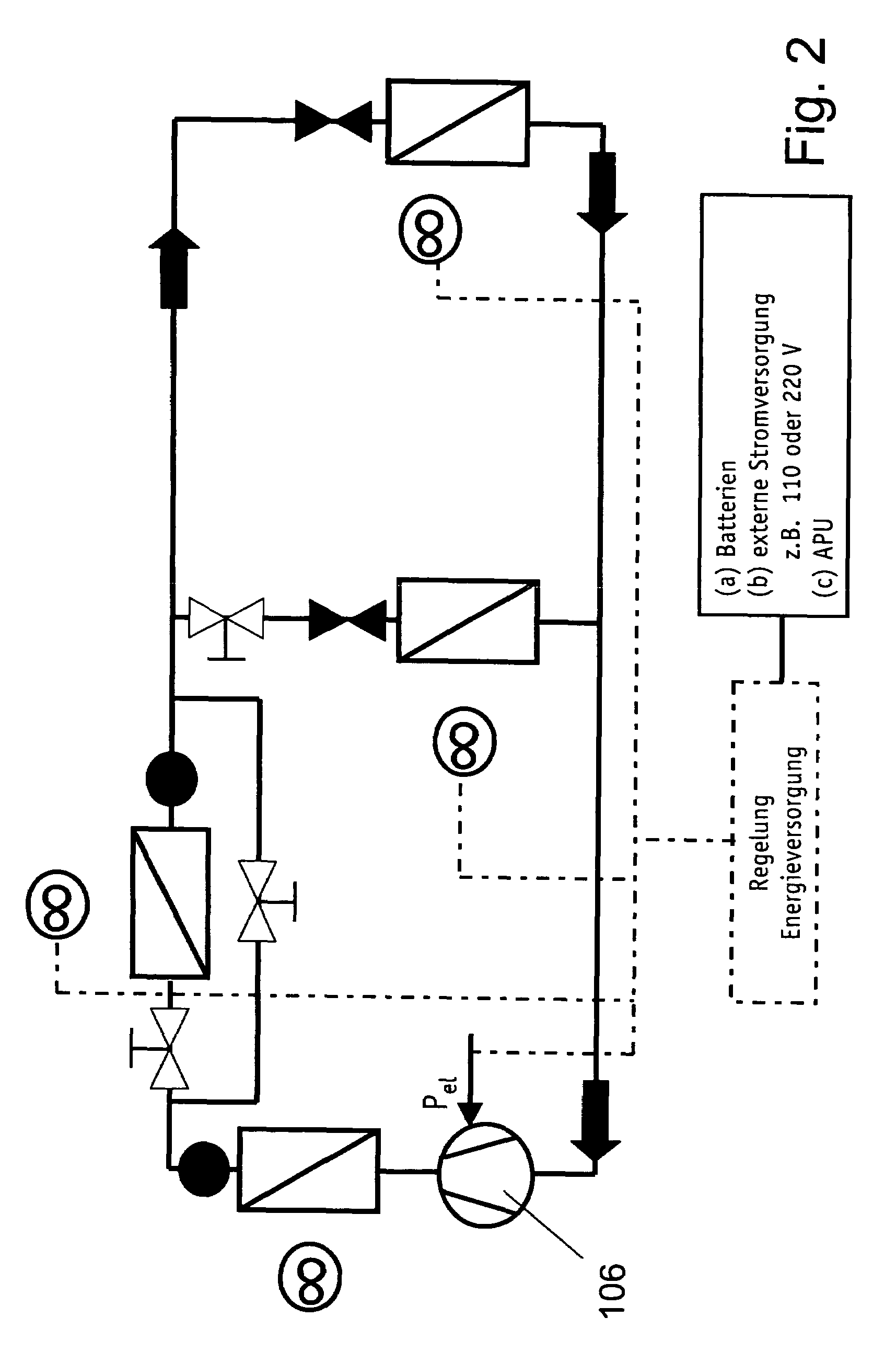
[0033]FIG. 2 illustrates a In this embodiment, only a single electrically driven compressor 106 circulates coolant both in normal operation and as needed in stationary operation. This single compressor replaces the parallel branches with mechanically driven compressor 5 and electrically driven compressor 6 of FIG. 1. The circuit thereafter operates as described above.

[0034]FIG. 3 illustrates yet another embodiment in which a hybrid compressor 205 / 206, which can be driven both mechanically by the engine and electrically, may be substituted for the single electrical compressor of FIG. 2. In normal operation, the running vehicle engine drives hybrid compressor 205 / 206, and, in stationary operation, an electrical source (such as batteries, an external power source or an APU) supplies power to compressor 205 / 206. In other respects, this embodiment is similar to the prior embodiments.

fourth embodiment

[0035]the invention is illustrated in FIG. 4. In this embodiment, the circuit 4 splits into two branches downstream of the junction of compressors 5 and 6. A first branch 411 can be closed off by a first valve 410, thereby forming a bypass to the second branch 413, which can be closed off by a second valve 412. In normal operation, first valve 410 is closed and second valve 412 is open, so that refrigerant flows through second branch 413 and thus through condenser 7, and, subsequently, through condenser 14.

[0036]In contrast to the first embodiment, the refrigerant circuit in FIG. 4 does not include a bypass for second condenser 14. Furthermore, receiver 16 is only arranged downstream of second condenser 14. Electrically driven fan 15 supplies cooling air receiver 16, but no air is needed nor supplied to a second receiver, such as receiver 9 in the embodiment of FIG. 1.

[0037]By reference to FIG. 4, the flow of refrigerant during normal operation will now be described. First compresso...


PUM


Abstract

The invention pertains to a stationary vehicle air conditioning system with a refrigerant circuit, in which at least one compressor circulates the refrigerant to at least two condensers. The at least one compressor may be powered by the vehicle's mechanical power, by an electrical source, or by a combination of these driving forces. Depending on desired operating characteristics, the condensers may be arranged in a series or parallel configuration. A second compressor also may be added, which second compressor may be powered by a source other than the mechanical energy of the vehicle's engine.

Description

CROSS-REFERENCE TO RELATED APPLICATIONS[0001]This patent application claims the benefit of German Patent Application No. DE 10 2004 042 691.0, filed Sep. 1, 2004, which is hereby incorporated by reference.FIELD OF THE INVENTION[0002]The invention pertains to a vehicle air conditioning system and method, and more particularly, to an air conditioning system that is particularly advantageous for use with a vehicle in which the engine is not running (a “stationary vehicle”). The invention may be employed, for example, with a truck having a first air conditioner in the driver's compartment and a second air conditioner in a sleeping compartment. The air conditioning system and method includes a plurality of components that may be operated in a first mode while the engine is running and in a second mode while the engine is not running.BACKGROUND OF THE INVENTION[0003]German patent application DE 44 14 547 A1 describes a stationary vehicle air conditioning system in which the vehicle engine...

Claims


Application Information

Patent Timeline
Patent Type & Authority Patents(United States)
IPC IPC(8): F25B41/04
CPCB60H1/322B60H1/3227B60H1/323F25B6/00F25B49/027B60H2001/3294F25B5/02F25B6/02F25B6/04F25B2400/0403F25B2400/075
Inventor HEBERLE, ARTHURWEINBRENNER, MARCUS
Owner BEHR GMBH & CO KG
Why Eureka
Try Eureka