Electronically controlled earth drilling rig

a technology of earth drilling and electric control, which is applied in the field of earth drilling, can solve the problems of broken carbide buttons, failure of hammer operation, etc., and achieve the effects of reducing effective weight, constant penetration rate, and reducing effective weigh

Active Publication Date: 2008-04-01
SCHRAMM INC
View PDF5 Cites 56 Cited by
  • Summary
  • Abstract
  • Description
  • Claims
  • Application Information

AI Technical Summary

Benefits of technology

[0009]The control also monitors the rate of penetration of the drill string, and regulates the speed of rotation of the drill string in response to the rate of penetration, while maintaining the effective weight of the drill string at a predetermined operating level, thereby maintaining a substantially constant rate of penetration.
[0010]The control can also be programmed to reduce the effective weight on the bit to a fraction of its predetermined operating level when the pressure of the compressed air delivered to the pneumatic hammer falls below a predetermined level during drilling, for example when a underground void is encountered by the drill bit. The control can also be programmed to monitor the torque in the drill string by monitoring the pressure of the hydraulic fluid driving the drill head, and can reduce the effective weight on the bit when the torque exceeds a predetermined torque level, for example, when the drill bit encounters a broken formation.
[0011]In addition, the controller can be programmed to cause the drill head to retract the drill string by a predetermined distance sufficient to raise the drill bit off the bottom of the bore hole and pause, when the drill head position sensor indicates that the drill head has approached the lower limit of its travel on the mast, and cause the drill head to continue to retract the drill string to a position at which an additional drill pipe section can be added to the drill string.

Problems solved by technology

That is, if the drill string is advanced against the bottom of a bore hole before the air pressure delivered to the hammer is sufficiently high, the hammer can fail to operate, and the downward force exerted on the bit can cause breakage of the carbide buttons.

Method used


Image

  • Electronically controlled earth drilling rig
  • Electronically controlled earth drilling rig
  • Electronically controlled earth drilling rig

Examples


Embodiment Construction

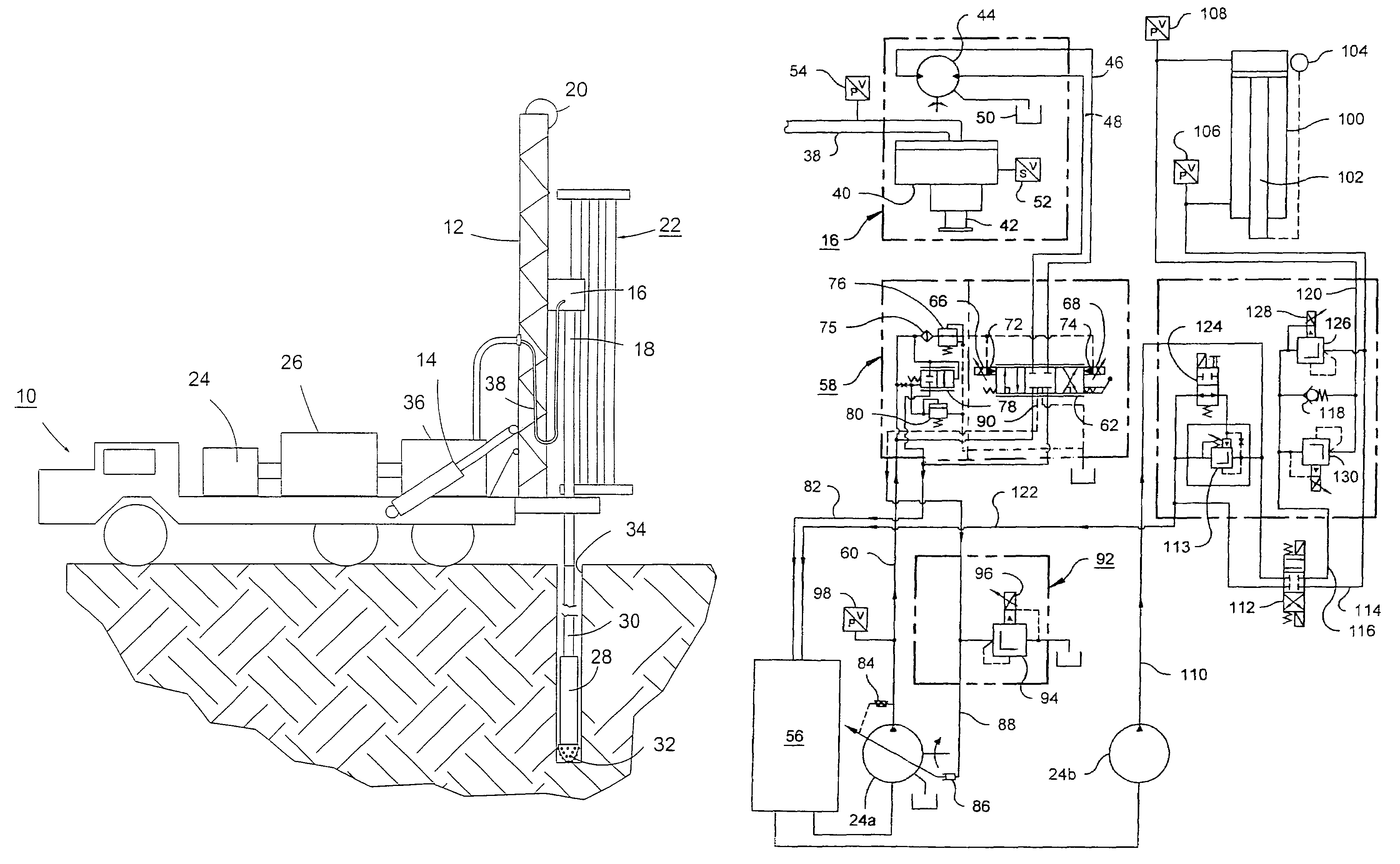
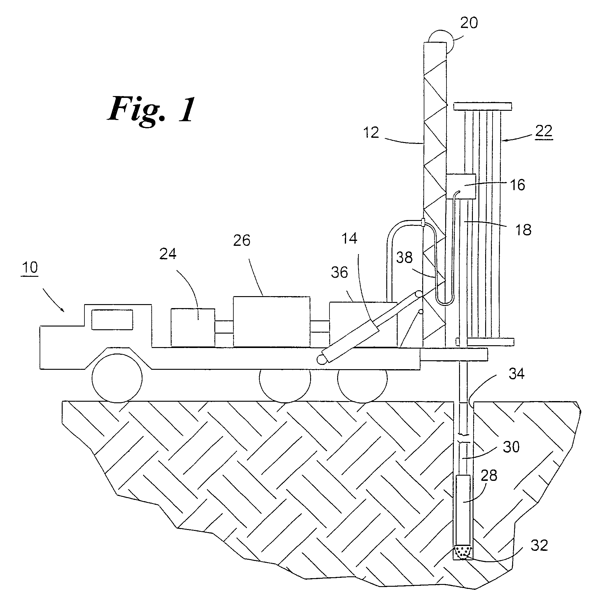
[0016]As shown in FIG. 1, a typical drilling rig is self-propelled, being incorporated onto a vehicle 10. The drilling rig includes an elongated mast 12, which is hinged to the vehicle, and tiltable by one or more hydraulic actuators 14 from a horizontal condition for transport, to a vertical condition, as shown, for drilling. The mast can also be held in an oblique condition for angle drilling.

[0017]A drill head 16, for rotating a drill string 18, is guided for longitudinal movement along the mast, and a hydraulically operated hoist 20 is provided for controlling movement of the drill head. The drill string is made up by connecting lengths of pipe supplied from a carousel 22 by means of a transfer mechanism (not shown).

[0018]A breakout mechanism (not shown) is provided for connecting and disconnecting lengths of drill pipe to and from one another and for connecting and disconnecting lengths of drill pipe to and from the drill head.

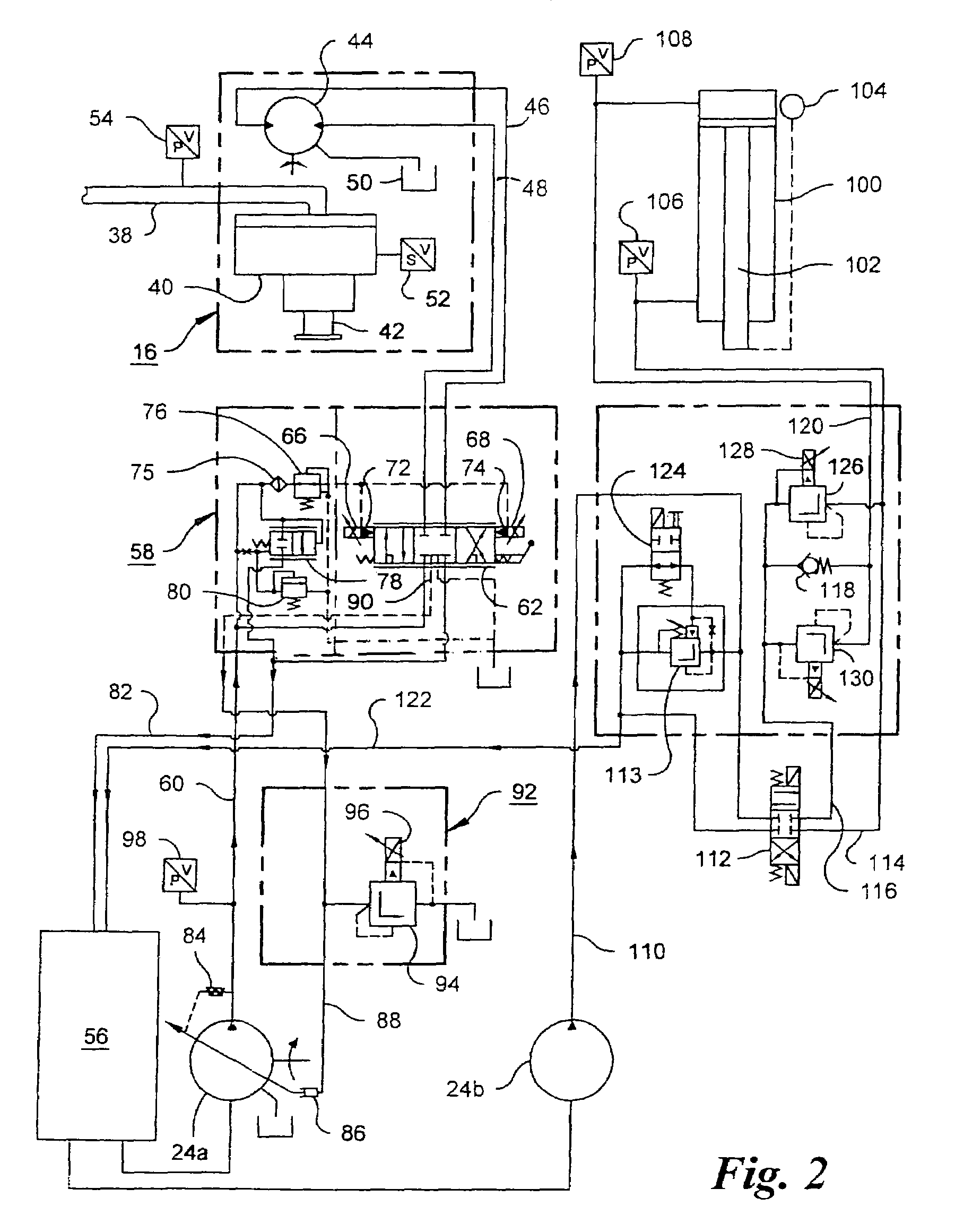
[0019]Hydraulic actuators for tilting the mast, ope...


PUM


Abstract

An electronic control, for automated earth drilling using a pneumatic hammer-operated bit, preliminarily weighs a drill string, and, during drilling, automatically maintains a desired weight on the bit, and also maintains a constant rate of drilling progress by regulating drill string rotation speed. The weight on the bit is automatically maintained at a fraction of the pre-established desired weight as the air pressure in the supply to the pneumatic hammer builds up to an operating level. The control detects voids and broken formations by monitoring air pressure and torque respectively, and responds by reducing the weight on the bit. The control automatically raises the drill bit though a short distance as the drill head reaches the lower limit of its travel, pauses until the air pressure drops, and then raises the drill string to a position for insertion of a new length of pipe.

Description

FIELD OF THE INVENTION[0001]This invention relates to earth drilling, and more particularly to a control system for improving drill performance.BACKGROUND OF THE INVENTION[0002]Earth drilling rigs, of the kind used to drill water wells, and for mineral exploration, etc., typically comprise a vehicle-mounted tilting mast, a drill head (sometimes referred to as a “gearbox” since a gear transmission is its principal component) movable up and down the mast by a hydraulic hoist, and a hydraulic motor carried by the drill head for rotating a drill string. A pneumatic hammer is typically provided at the bottom of the drill string for repeatedly striking an anvil at the top of a drill bit. The bit typically has an array of carbide buttons for cutting rock. Hydraulic fluid and compressed air are provided by pumps and a compressor mounted on the vehicle and operated by an engine also mounted on the vehicle.[0003]Drilling requires skill and experience for several reasons. Efficient drilling re...

Claims


Application Information

Patent Timeline
Patent Type & Authority Patents(United States)
IPC IPC(8): E21B19/084B23Q15/12E21B44/02
CPCE21B7/022E21B44/02
Inventor BROOKOVER, BRIAN DAVID
Owner SCHRAMM INC
Why Eureka
Try Eureka