Rotating concave eddy current probe

a concave eddy current and eddy current probe technology, applied in the direction of magnetic property measurement, instruments, material magnetic variables, etc., can solve the problems of weak eddy current flowing deeper in the material, lag in phase, and uneven distribution of eddy currents induced by ec probe test coils, etc., to overcome inspection impediments.

Active Publication Date: 2008-04-01
NAT TECH & ENG SOLUTIONS OF SANDIA LLC
View PDF8 Cites 30 Cited by
  • Summary
  • Abstract
  • Description
  • Claims
  • Application Information

AI Technical Summary

Benefits of technology

[0017]A rotating concave eddy current probe for detecting fatigue cracks hidden from view underneath the head of a raised head fastener, such as a buttonhead-type rivet, used to join together structural skins, such as aluminum aircraft skins. The probe has a recessed concave dimple in its bottom surface that closely conforms to the shape of the raised head. The concave dimple holds the probe in good alignment on top of ...

Problems solved by technology

However, eddy currents flowing deeper in the material are weaker, and lag in phase, compared to the eddy currents near the surface or at an inner wall.
Eddy currents induced by an EC probe test coil are not uniformly distributed throughout the conductive skin.
This loss in sensitivity caused by the “lift-off” effect is significant when the EC probe is placed on top of the head of a raised head fastener, especially when trying to detect cracks in the structural member (i.e., skin) directly underneath the fastener's head (a typical raised head rivet can have a lift-off distance of as much as 1-3 mm).
Raised head fasteners (e.g., rivets) that are typically found in rotorcraft joints, aircraft fuselage frames, and many civilian structures (ships, bridges, towers, etc), interfere with the ability to place conventional eddy current probes close to the area of interest; i.e., the structural skin underneath the raised head fastener.
It is difficult, if not impossible, with current technology (i.e., conventional EC probes) to generate sufficient eddy current fields under the fastener head for crack detection.
When using any hand-held EC probes on raised head fasteners it is difficult to provide a consistent and stable orientation of the test coil with respect to the radial and circumferential position (relative to the rivet's centerline).
It is also difficult to maintain the orientation of the coil's axis perpendicular to the rivet head's surface.
Uncontrollable changes in the probes position and orientation as the probe is manually moved around on the rivet head and on the ski...

Method used


Image

  • Rotating concave eddy current probe
  • Rotating concave eddy current probe
  • Rotating concave eddy current probe

Examples


Embodiment Construction

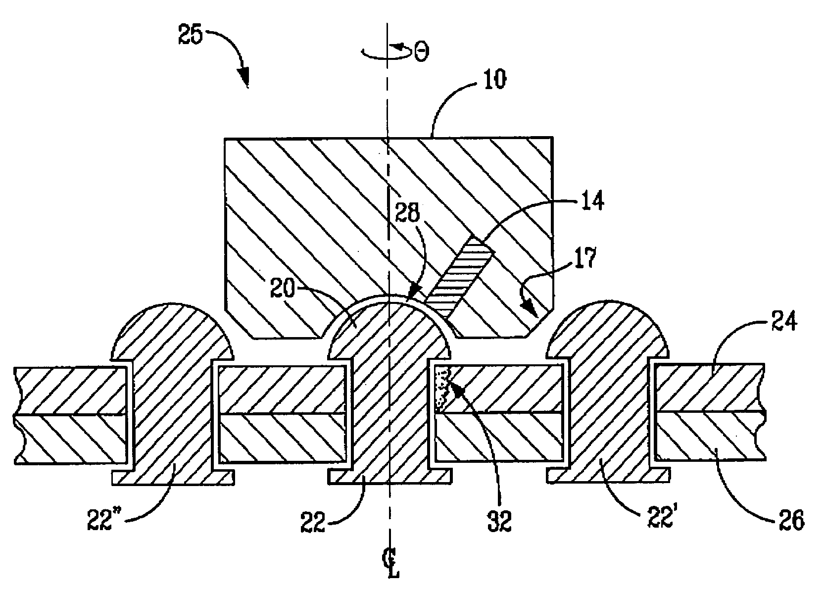
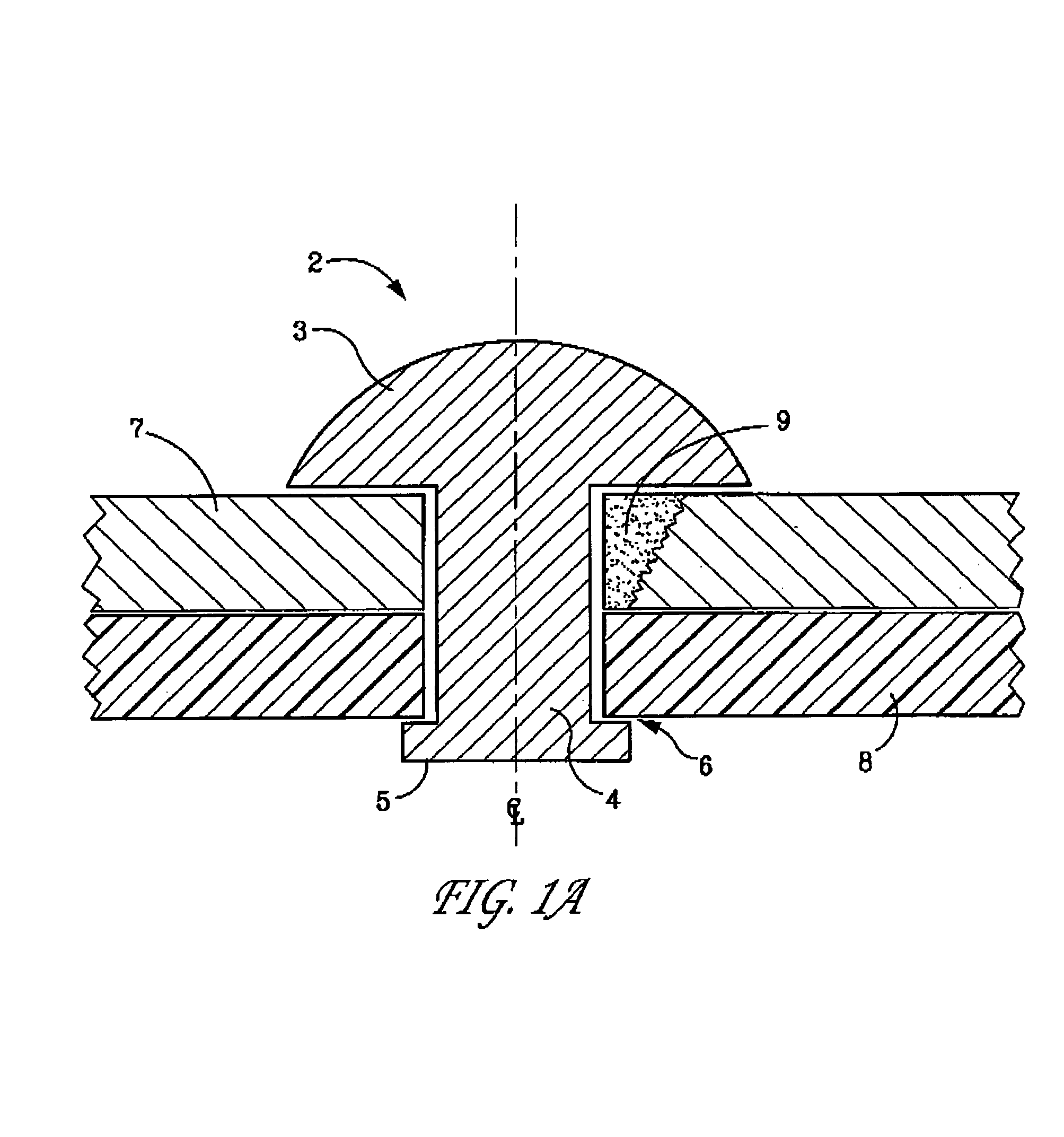
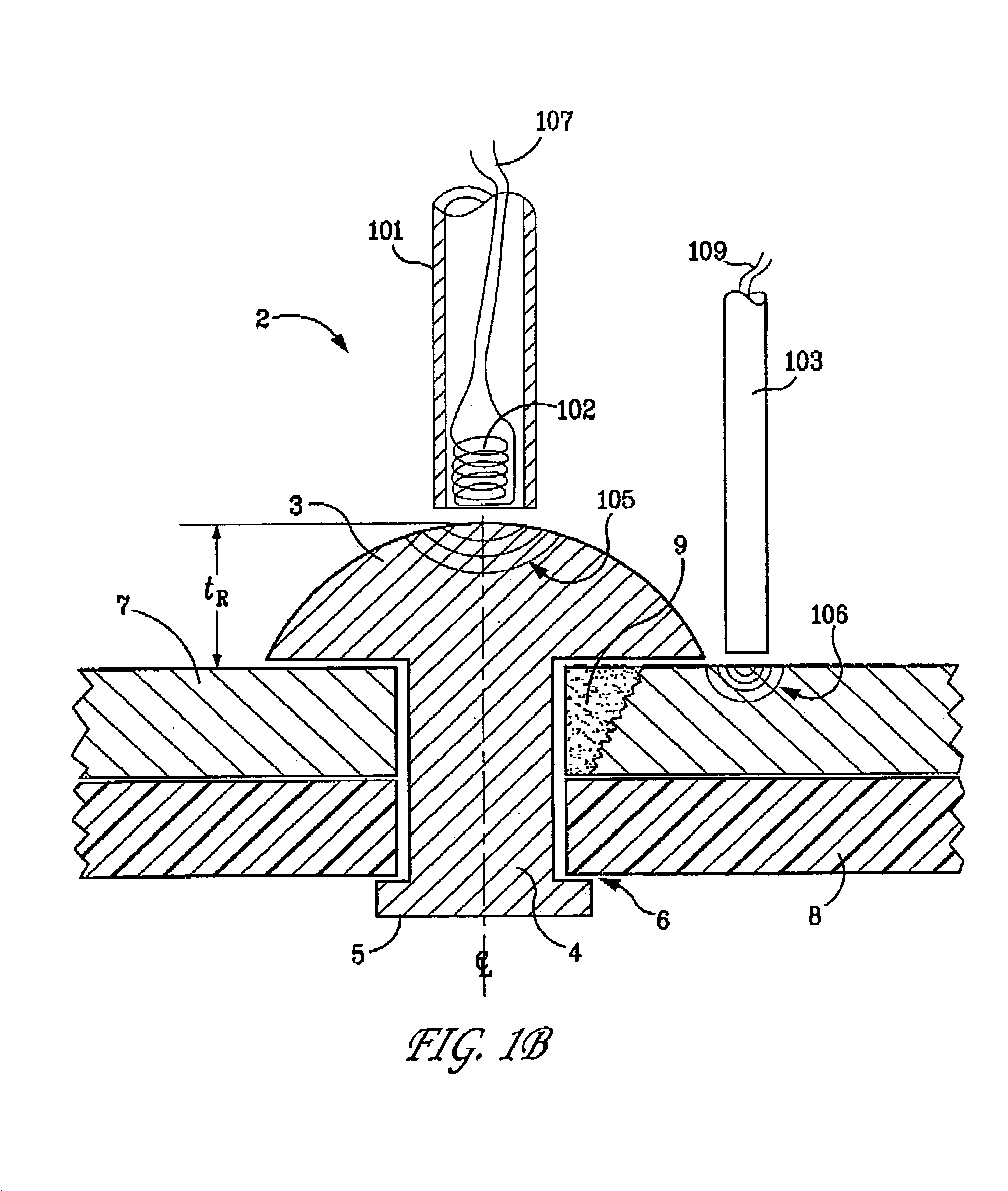
[0039]The term “rivet” is broadly defined herein to mean any type of “raised head” fastener. Thus, the term “rivet” includes screws, bolts, carriage bolts, stove bolts, solid rivets, blind rivets, multi-grip rivets, grooved rivets, tubular rivets, etc. The term “raised head” includes the following shapes: round head, universal head, brazier head, flat head, rounded head, domed head, pan head, pan head with chamfered outer edge, button head, truss head, cheese head, fillister head, socket head, countersunk with a rounded top, etc. These shapes are typically axisymmetric with respect to the fastener's central axis of revolution (centerline). Metals commonly used for raised head fasteners include steel, aluminum, titanium, brass, bronze, nickel alloys, etc. The term “non-conducting” means non-electrical conducting. The term “rotating eddy current probe means that the probe body is rotatable (i.e., can be rotated) during inspection around the central axis of the raised head rivet, eithe...


PUM


Abstract

A rotating concave eddy current probe for detecting fatigue cracks hidden from view underneath the head of a raised head fastener, such as a buttonhead-type rivet, used to join together structural skins, such as aluminum aircraft skins. The probe has a recessed concave dimple in its bottom surface that closely conforms to the shape of the raised head. The concave dimple holds the probe in good alignment on top of the rivet while the probe is rotated around the rivet's centerline. One or more magnetic coils are rigidly embedded within the probe's cylindrical body, which is made of a non-conducting material. This design overcomes the inspection impediment associated with widely varying conductivity in fastened joints.

Description

FEDERALLY SPONSORED RESEARCH[0001]The United States Government has rights in this invention pursuant to Department of Energy Contract No. DE-AC04-94AL85000 with Sandia Corporation.CROSS-REFERENCE TO RELATED APPLICATIONS[0002]This application has technical disclosure in common with U.S. application Ser. No. 11 / 664,665 filed Apr. 4, 2007.BACKGROUND OF THE INVENTION[0003]The present invention relates generally to methods and apparatus for using eddy current probes to non-destructively inspect and detect the presence of hidden fatigue cracks located underneath the head of a raised head fastener, such as raised head rivets used in joining aluminum skins of aircraft fuselages or bridge assembly girders.[0004]Eddy Current (EC) inspection techniques use the principles of electromagnetic induction to identify or differentiate changes in structural conditions in conductive materials (e.g., metals). The presence of a crack is indicated by localized changes or perturbations in the flow of eddy ...

Claims


Application Information

Patent Timeline
IPC IPC(8): G01N27/82G01R33/12
CPCG01N27/9033G01R33/028G01R33/12G01N27/9006
Inventor ROACH, DENNIS P.WALKINGTON, PHILRACKOW, KIRK A.HOHMAN, ED
Owner NAT TECH & ENG SOLUTIONS OF SANDIA LLC
Why Eureka
Try Eureka