Eureka AIR delivers breakthrough ideas for toughest innovation challenges, trusted by R&D personnel around the world.

Data collision detection device and method

Active Publication Date: 2008-04-01
COLDER PRODS
View PDF37 Cites 38 Cited by
  • Summary
  • Abstract
  • Description
  • Claims
  • Application Information

AI Technical Summary

Benefits of technology

[0017]Embodiments of the present invention provide a data collision detection device that can operate where the read / write distance remains relatively constant, and has simplified circuitry for demodulating and recovering the subcarrier signal. Further, as the data signal received from the data transmitter is directly decoded from the recovered subcarrier modulated signal, a multi-bit analog to digital converter, used for instance in existing devices, is not needed. In this configuration, data collisions can be detected more quickly and conveniently without the need for such an analog to digital converter. Further, this configuration also saves space needed for such devices.

Problems solved by technology

However, existing designs and methods can require additional filtering and amplification to convert the subcarrier signal to a baseband signal.
These additional stages for converting the signal so that it may be decoded can result in slower performance in the communication, for instance, between an interrogator and an RFID tag, and more particularly can result in slower detection of the occurrence of data collisions.

Method used


Image

  • Data collision detection device and method
  • Data collision detection device and method
  • Data collision detection device and method

Examples


Embodiment Construction

[0025]In the following description of the illustrated embodiments, reference is made to the accompanying drawings that form a part hereof. It is to be understood that other embodiments may be utilized as structural changes may be made without departing from the spirit and scope of the present invention.

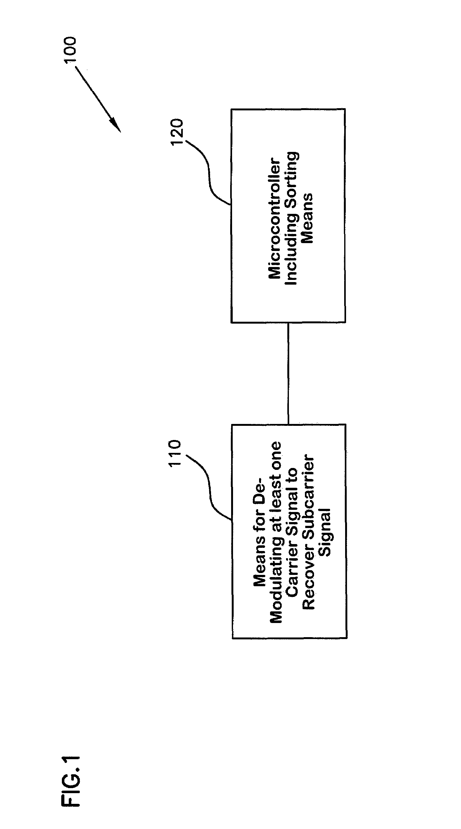
[0026]FIG. 1 illustrates one embodiment of a data collision detection device 100. The data collision detection device includes a means for de-modulating at least one carrier signal 110 in providing a subcarrier signal.

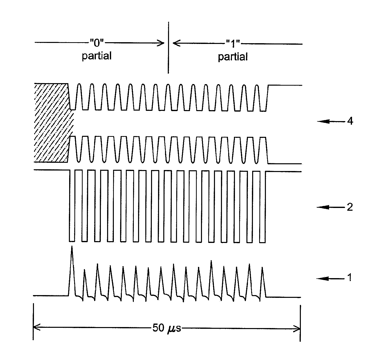
[0027]Preferably, in one illustrated embodiment the carrier signal(s) is received from transmitters or transponders such as RFID tags, and represents data contained in the tag. In one example, an amplitude shift keying modulator circuit, implemented for instance in an RFID tag, is activated where a control signal is applied to the output stage in providing a modulated subcarrier signal from the carrier signal(s) to an interrogator (further discussed below in FIG. 3).

[002...


PUM


Abstract

A data collision detection device that includes a means for de-modulating at least one carrier signal corresponding to a received modulated subcarrier signal from at least one data transmitter to recover the subcarrier signal from the carrier signal. A microcontroller is operatively connected with the means for recovering a subcarrier signal. The microcontroller includes a means for decoding a recovered subcarrier signal. The means for decoding the recovered subcarrier signal is capable of interpreting signal transitions in the recovered subcarrier signal, and is capable of detecting data collisions in the recovered subcarrier signal when in the presence of a plurality of modulated subcarrier signals.

Description

CROSS REFERENCE TO RELATED APPLICATION[0001]This application claims the benefit under Title 35, United States Code § 119(e), of U.S. Patent Provisional Application Ser. No. 60 / 417,357, filed Oct. 8, 2002 and entitled “Data Collision Detection Device and Method for the Same,” which is hereby incorporated by reference in its entirety.FIELD OF THE INVENTION[0002]This invention generally relates to a device for decoding received data signals from data transmitters and a method for detecting data collisions from a multitude of received data signals. More particularly, this invention is related to a data collision detection device and method for detecting data collisions for use in radio frequency identification (RFID) tag interrogator devices.BACKGROUND OF THE INVENTION[0003]Devices employing capabilities for detecting and sorting data collisions in transmitted signals have been known and are widely used. One example of this is implemented in systems using interrogators or read / write dev...

Claims


Application Information

Patent Timeline
IPC IPC(8): H04L12/413G06K7/00
CPCG06K7/0008G06K7/10029
Inventor GARBER, RICHARD STEWART
Owner COLDER PRODS
Why Eureka
Eureka Blog
Learn More