Hybrid power system for continuous reliable power at locations including remote locations

a power system and hybrid technology, applied in the direction of liquid degasification, separation process, fused electrolyte fuel cell, etc., can solve the problems of short-term standby power using batteries that is distinct from the disadvantage the failure of the whole battery pack,

Inactive Publication Date: 2008-04-08
ORMAT TECH INC
View PDF9 Cites 43 Cited by
  • Summary
  • Abstract
  • Description
  • Claims
  • Application Information

AI Technical Summary

Problems solved by technology

The requirements for reliable power supply are more and more stringent with the advance of modern industry, computer and telecommunications systems and with the increasing costs of non-supply electricity.
The short term standby power using batteries has a distinct disadvantage when failures occur.
This is especially true since there is no satisfactory diagnostic system to detect failures of batteries on standby: a single cell failure can cause failure of the whole battery pack.
Expensive climate control and limited life are also drawbacks of battery systems.
The diesel generators used for longer periods of standby operation, however, have problems of unreliable startups and require frequent maintenance and periodic overhaul.
Fuel cells and stirling engines can also be used but fuel cells have too long of a startup process and these systems are still in the development stage and have no proven reliability.
However, the reliability of such systems can be questionable.
Further, the included large batteries typically require climate control in the form of heating or air conditioning, thus increasing the complexity and fuel consumption of the system for a given load.
The cost of nickel-cadmium batteries is very high.
In addition to the high cost of batteries, the life-span of these batteries is usually less than 10 years.
Maintenance, vandalism and theft of the batteries of photovoltaic are additional concerns for photovoltaic systems.
Photovoltaic systems having a diesel generator back-up share the same problems as the previously-mentioned strictly photovoltaic systems, namely, cost, life-span and maintenance of batteries as well as risk of vandalism and theft.
In addition, utilizing a diesel generator as a back-up power source can produce reliability issues as the system redundancy depends on an unreliable diesel engine start.
The high fuel consumption is aggravated by the fact that a TEG system is a constant power device that requires a dummy load for dissipating any excess energy and, thus requiring additional fuel consumption due to the over-sizing of the unit, output variations due to ambient conditions or varying load requirements.
If additional batteries are not used, the battery will not be properly charged and will require additional maintenance and manual charging during maintenance and thus the life span of the battery will decrease.
Additionally, TEG systems have a high fuel consumption and the life span of a TEG system is typically less than 10 years.
However, the fuel cell technology is not mature and the life and reliability of the fuel cells are not sufficient to maintain reliable remote power without a proven backup for when the fuel cell fails.

Method used


Image

  • Hybrid power system for continuous reliable power at locations including remote locations
  • Hybrid power system for continuous reliable power at locations including remote locations
  • Hybrid power system for continuous reliable power at locations including remote locations

Examples


Embodiment Construction

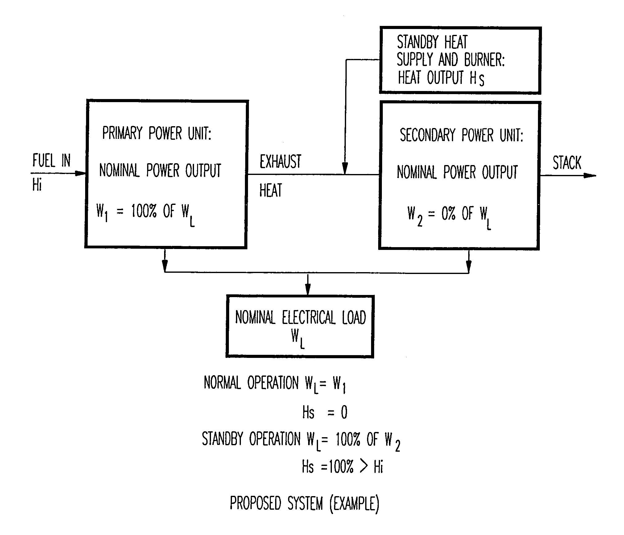
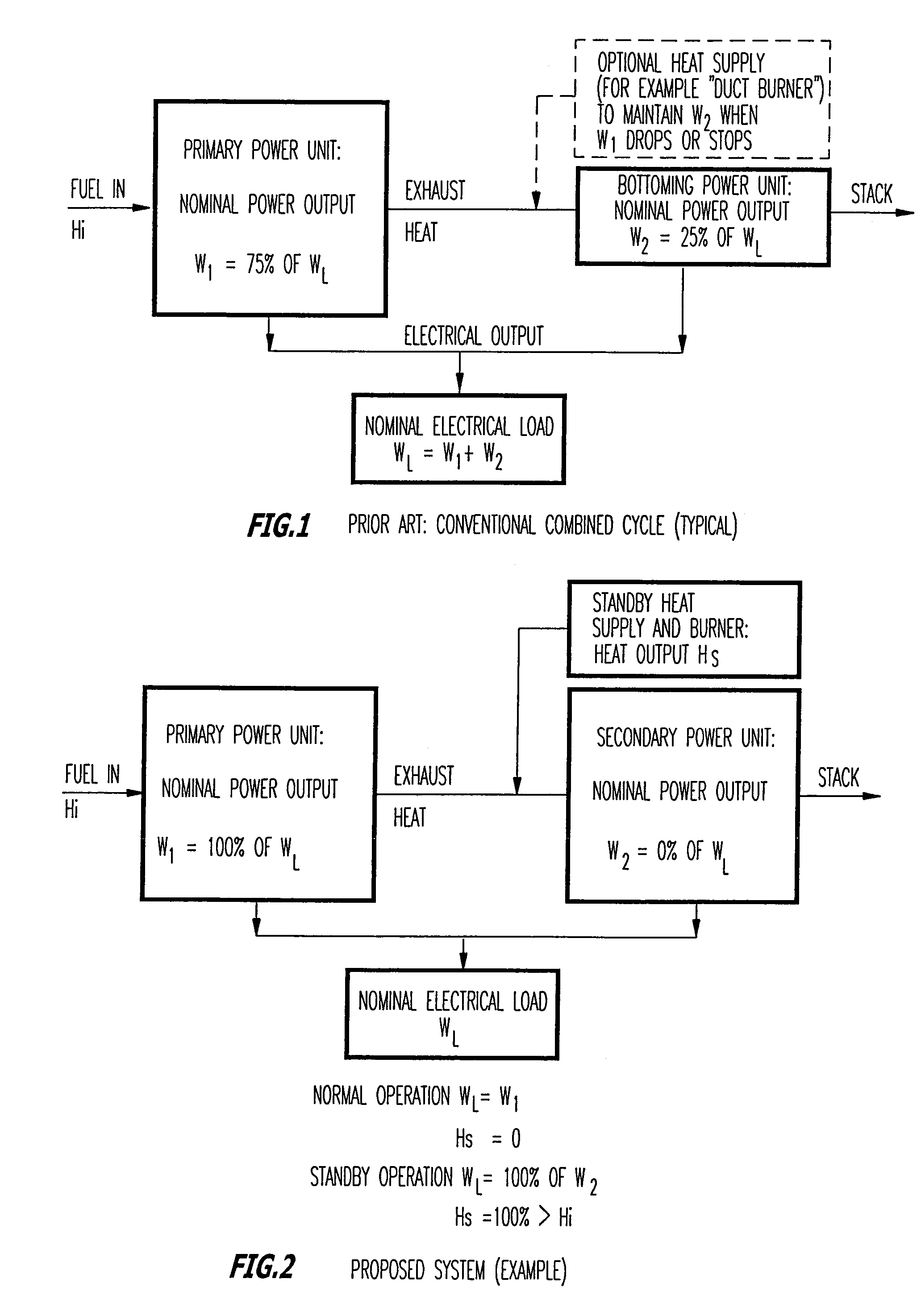
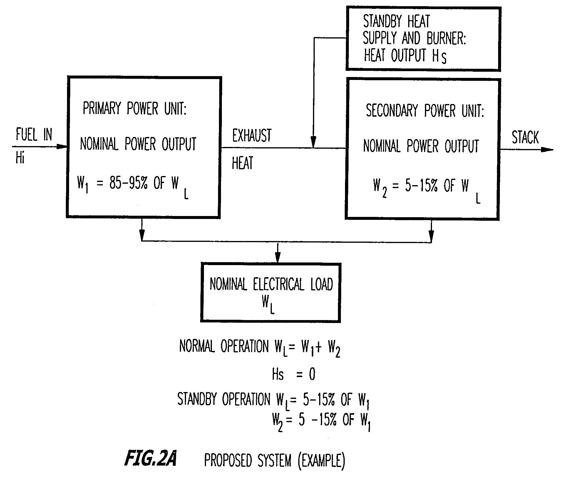
[0040]Turning now to the Figures, FIG. 1 represents a conventional high-efficiency combined-cycle power plant that is well-known in the art. As can be seen from the figure, fuel is supplied to a primary power unit which produces nominal power output. The power output of the primary power unit is generally about 60-80% of the required load. Heat is also exhausted from the primary power unit and supplied to a bottoming power unit, wherein power is produced and supplied to the load. In the conventional combined-cycle power plant as shown in FIG. 1, the ability of the bottoming power unit to produce electricity depends on the exhausted heat from the primary power unit. In other words, if the primary power unit suddenly stops working, the heat to the bottoming unit also stops and the bottoming power unit no longer is able to function.

[0041]The cascading heat from the primary power unit to the bottoming power unit increases the overall efficiency of the combined-cycle power plant in that ...


PUM

PropertyMeasurementUnit
power levelaaaaaaaaaa
electric poweraaaaaaaaaa
alternating currentaaaaaaaaaa

Abstract

The present inventive subject matter is drawn to a hybrid ultra reliable power generating system for supplying continuous reliable power at remote locations comprising: a primary power unit producing electric power that is supplied to a load. Also a secondary power unit is included in the form of a closed cycle vapor turbine (CCVT) system that is capable of producing 100% of the electric power that is produced by the primary power unit and which is heated in hot standby by rejected heat of the primary power unit, wherein the vaporizer of the CCVT is maintained during hot standby at a temperature above its nominal operating temperature and the vapor turbine of the CCVT is preferable maintained at idle during hot standby at a rotating speed. Furthermore, the present inventive subject matter is drawn to an apparatus that combines a fuel efficient primary power generation unit system such as a high temperature fuel cell with a secondary power unit that is a very high reliability closed cycle vapor turbine (CCVT) which operates according to a Rankine cycle using organic working fluid that is capable of producing approximately 5-15% of the electric power that is produced by the primary power unit and which is heated by rejected heat of the primary power unit, wherein working fluid in the vaporizer of the CCVT is heated by the heat rejected by the primary power unit.

Description

BACKGROUND OF THE INVENTION[0001]1. Technical Field[0002]This invention relates to a method and apparatus for producing power, and more particularly, to a method and apparatus for producing ultra-reliable power with redundancy which requires little maintenance or supervision and with improved fuel consumption.[0003]2. Background of the Invention[0004]The requirements for reliable power supply are more and more stringent with the advance of modern industry, computer and telecommunications systems and with the increasing costs of non-supply electricity. This particularly applies for on-site generation of electricity, be it for grid connected and distributed generation or off-grid prime power supply at remote locations. The conventional solutions for providing high efficiency on-site generation of electricity include, for short periods of interruption, battery or flywheel uninterruptible power supply (UPS) systems are used; and for longer periods, engine driven generators such as diese...

Claims


Application Information

Patent Timeline
Patent Type & Authority Patents(United States)
IPC IPC(8): F01K13/02F01K13/00F01K23/06F01K23/10F01K25/08H01M8/12H01M8/14H01M16/00
CPCF01K13/00F01K13/02F01K23/02F01K23/065F01K23/101F01K25/08F01K27/02H01M16/003H01M2008/1293H01M2008/147H01M2250/402H01M2250/405Y02B90/12Y02E20/16Y02E60/525Y02E60/526Y02B90/16Y02B90/10Y02E60/50
Inventor BRONICKI, LUCIEN Y.
Owner ORMAT TECH INC
Why Eureka
Try Eureka