
Voltage conversion device and computer-readable recording medium having program recorded thereon for computer to control voltage conversion

a voltage conversion device and computer-readable technology, applied in the direction of dc-ac conversion without reversal, process and machine control, instruments, etc., can solve the problems of motor drive apparatus, overvoltage and overcurrent, increase in deviation between voltage command and output voltage, etc., to suppress the generation of overvoltage and overcurrent

Active Publication Date: 2008-04-08
TOYOTA JIDOSHA KK
View PDF16 Cites 22 Cited by
  • Summary
  • Abstract
  • Description
  • Claims
  • Application Information

AI Technical Summary

Benefits of technology

The present invention provides a voltage conversion device that converts a DC voltage into an output voltage while suppressing overvoltage and overcurrent. The device includes a voltage converter, a detection unit, and a control unit. The control unit conducts feedback control of the voltage converter in a way that the output voltage is equal to a target voltage. This feedback control is done by changing the voltage command of the voltage converter in response to any deviation between the target voltage and the detected output voltage. The device can be used in a computer-readable recording medium to control voltage conversion. Overall, the invention provides a reliable and effective solution for voltage conversion.

Problems solved by technology

The conventional motor drive apparatus, however, encounters a problem of overvoltage and overcurrent that could be generated when the feedback control is conducted for making the output voltage equal to the voltage command in such a case where the output voltage of the bidirectional converter varies due to a variation of a load applied to the motor.
Referring to FIG. 10, as the load applied to the motor increases, the output voltage of the bidirectional converter decreases below the voltage command, resulting in an increase in deviation between the voltage command and the output voltage.
In such a case, if a proportional gain and an integral gain determined according to the deviation are used to carry out the feedback control, the output voltage of the bidirectional converter exceeds the level of the overvoltage to cause the problem of generation of overvoltage and overcurrent.
More specifically, since the proportional gain increases according to the deviation and the integral gain increases due to integration of the deviation, the output voltage of the bidirectional converter sharply increases to exceed the overvoltage level, resulting in generation of the overvoltage and overcurrent.

Method used


Image

  • Voltage conversion device and computer-readable recording medium having program recorded thereon for computer to control voltage conversion
  • Voltage conversion device and computer-readable recording medium having program recorded thereon for computer to control voltage conversion
  • Voltage conversion device and computer-readable recording medium having program recorded thereon for computer to control voltage conversion

Examples


Embodiment Construction

[0036]An embodiment of the present invention is hereinafter described in detail with reference to the drawings. Like components in the drawings are denoted by like reference characters and the description thereof is not repeated here.

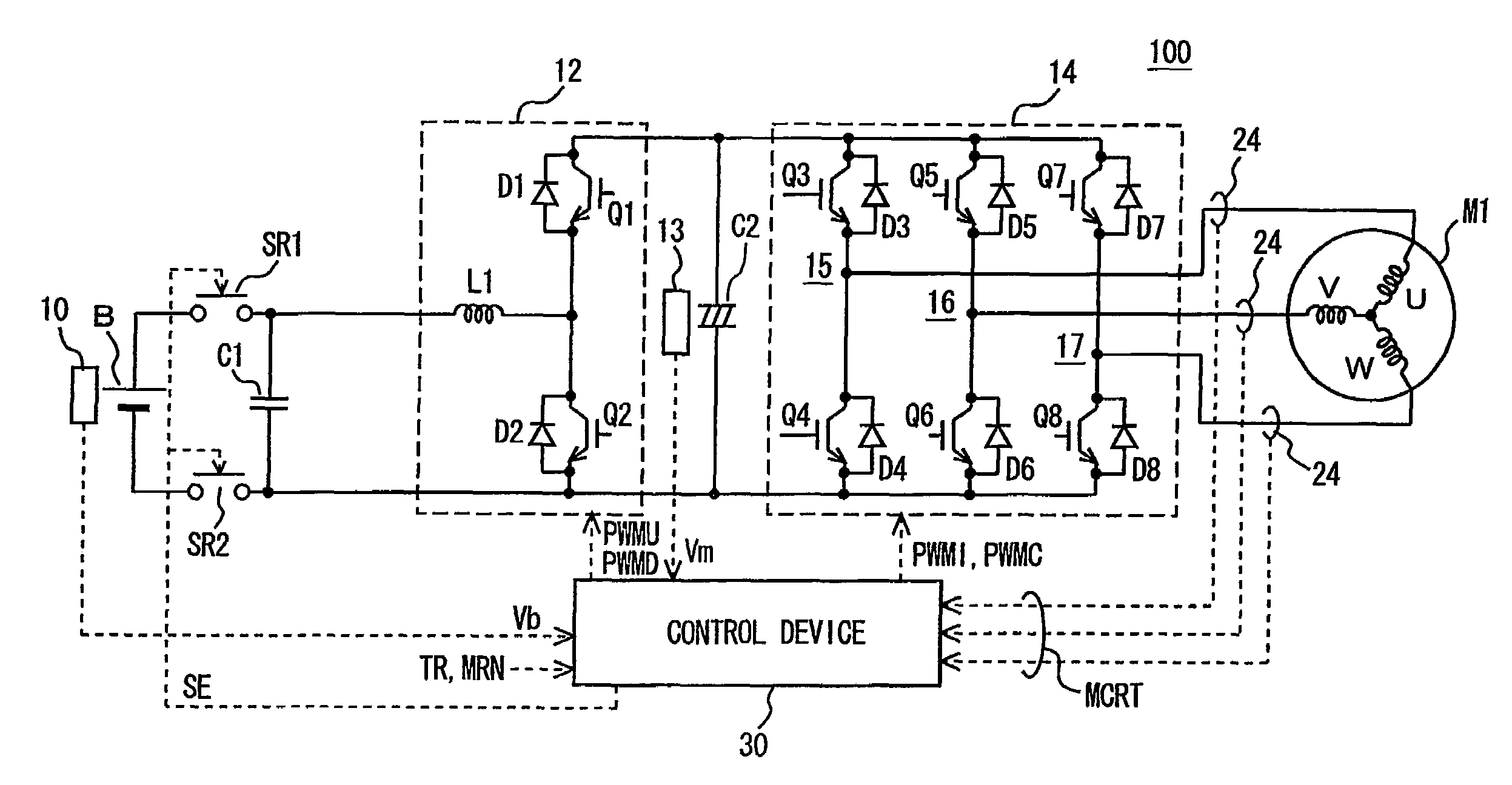
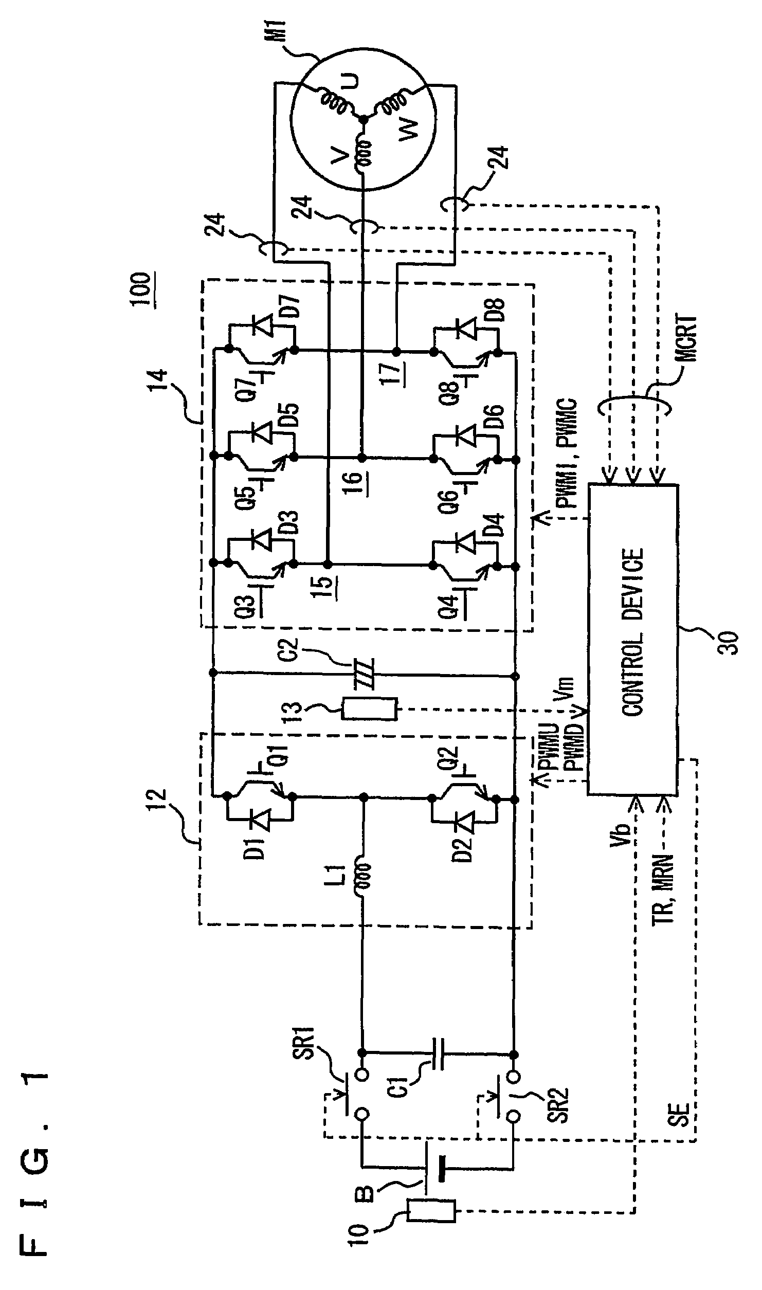
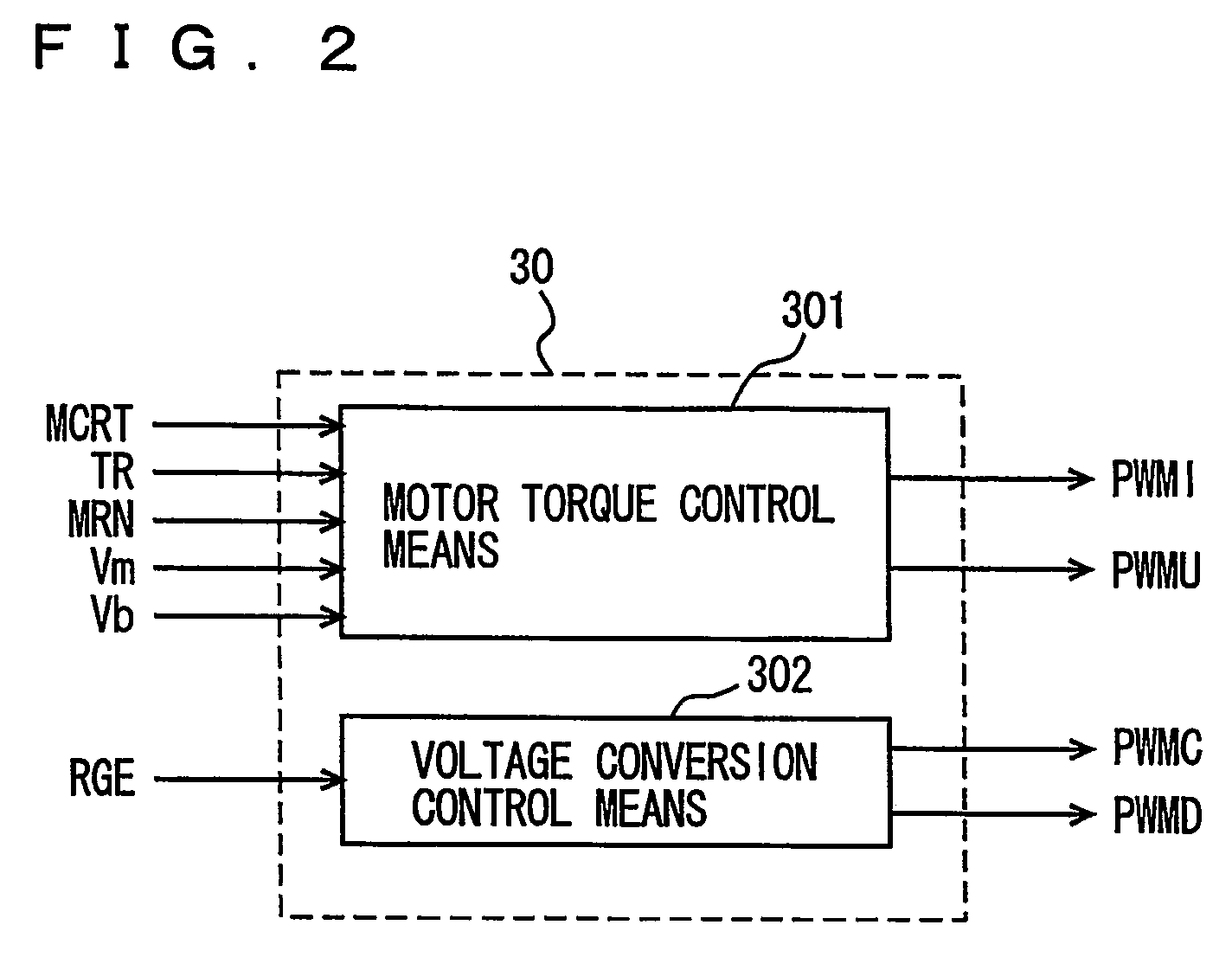
[0037]Referring to FIG. 1, a motor drive apparatus 100 having a voltage conversion device according to this embodiment of the present invention includes a DC power supply B, voltage sensors 10 and 13, system relays SR1 and SR2, capacitors C1 and C2, a voltage step-up converter 12, an inverter 14, electric-current sensors 24, and a control device 30. An AC motor M1 is a drive motor generating torque for driving drive wheels of a hybrid vehicle or electric vehicle. Alternatively, the motor may be mounted on a hybrid vehicle to function as an electric generator driven by the engine as well as an electric motor for the engine and thus have the ability to start the engine for example.

[0038]Voltage step-up converter 12 includes a reactor L1, NPN transistors Q...


PUM


Abstract

In a case where the deviation between a target voltage (Vdc_com1) and an output voltage (Vm) is larger than a specified value (A), a voltage command (Vdc_com2) of a voltage step-up converter (12) is calculated by adding the specified value (A) to the output voltage (Vm). When the output voltage (Vm) having been decreasing starts to increase, the voltage command (Vdc_com2) is calculated in such a manner that the rate of change of the voltage command (Vdc_com2) is equal to or smaller than a standard value. Using the calculated voltage command (Vdc_com2), feedback control of the voltage step-up converter is conducted in such a manner that the output voltage (Vm) is equal to the target voltage (Vdc_com1).

Description

TECHNICAL FIELD[0001]The present invention relates to a voltage conversion device converting a DC (direct current) voltage from a DC power supply into a target voltage and to a computer-readable recording medium having a program recorded thereon for a computer to control voltage conversion of a DC voltage into a target voltage.BACKGROUND ART[0002]Hybrid vehicles and electric vehicles have recently been of great interest as environment-friendly vehicles. The hybrid vehicles are now partially commercialized.[0003]A hybrid vehicle has, as its motive power sources, a DC power supply, an inverter and a motor driven by the inverter in addition to a conventional engine. More specifically, the engine is driven to secure the motive power source and a DC voltage from the DC power supply is converted by the inverter into an AC (alternating current) voltage to be used for rotating the motor and thereby securing the motive power source as well. An electric vehicle refers to a vehicle that has, a...

Claims


Application Information

Patent Timeline
Patent Type & Authority Patents(United States)
IPC IPC(8): H02M7/5387B60L9/18B60L50/15H02M7/48H02P27/06
CPCH02M7/53873B60L11/12Y02T10/7077B60L2210/14Y02T10/7225B60L50/15Y02T10/7072Y02T10/72
Inventor OKAMURA, MASAKI
Owner TOYOTA JIDOSHA KK
Learn More