
Magneto-optical disk and recording and/or reproducing method and recording and/or reproducing apparatus using the magneto-optical disk

a magneto-optical disk and magnetic field technology, applied in the field of magneto-optical disks, can solve the problems of serious copyright infringement of video, inability to control the optical head, and inability to record and reproduce disks on mini-discs, so as to prevent copyright infringement of the first information due to illegal action, the effect of increasing the recording capacity of the magneto-optical disk

Inactive Publication Date: 2008-04-08
SONY CORP
View PDF17 Cites 4 Cited by
  • Summary
  • Abstract
  • Description
  • Claims
  • Application Information

AI Technical Summary

Benefits of technology

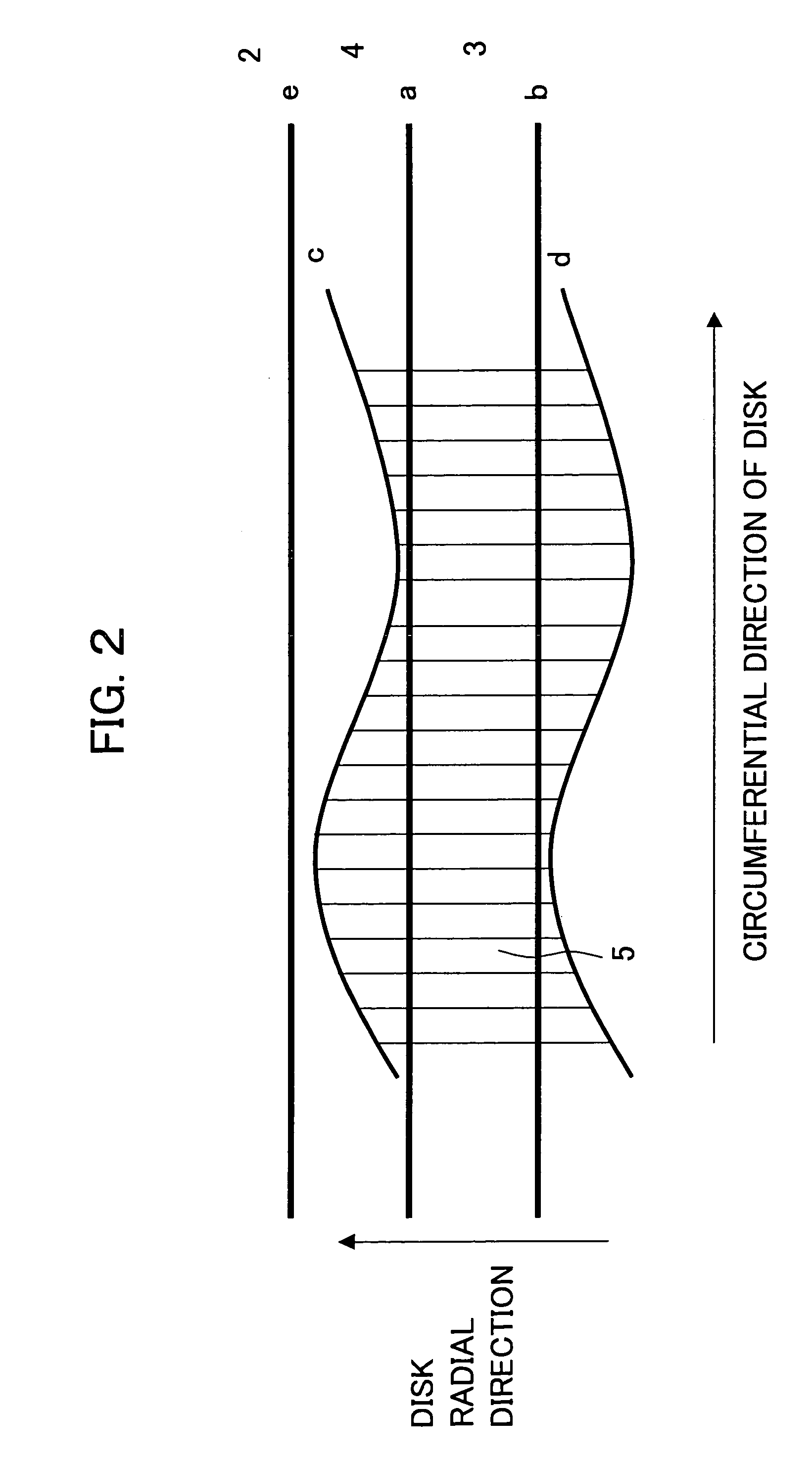
[0050]Due to this, it is possible to effectively utilize the space in which the mark array recording the second information meanders to record and reproduce third information. Further, reproduction error of the second information due to meandering of the mark array is prevented. According to the magneto-optical disk of the present invention, a disk having a small-sized diameter can be increased in recording capacity.
[0057]Due to this, it becomes possible to reproduce first information recorded in the main recording region and second information recorded in the sub recording region and the buffer region under preferred conditions. Specifically, the first information is reproduced by utilizing the MSR reproduction system. On the other hand, the second information is reproduced with a low noise by differential detection not utilizing the MSR reproduction system. Accordingly, good reproducing characteristics are obtained. The reproduction of the first information is controlled and managed by the second information, so infringement of the copyright for the first information is prevented. Further, since the MSSR reproduction system is utilized for the reproduction of the first information, the recording density of the main recording region can be raised and the magneto-optical disk can be increased in recording capacity.
[0059]In the reproducing method and apparatus of the magneto-optical disk of the present invention, preferably provision is further made of a step of (means for) control according to the reproduced second information to record or reproduce the first information in the main recording region. Due to this, even in a disk having a small-sized diameter, it becomes possible to perform high density recording and record disk discrimination information. Accordingly, infringement of the copyright for the first information due to illegal action is prevented.

Problems solved by technology

There is no deterioration in quality due to copying of the data in the digital video, therefore when illegal copies are made, high quality copies are illegally produced and the copyright of the video is seriously infringed.
When the optical head skips over the control data region from the disk outer circumference side to access the PCA region, however, control of the optical head becomes impossible.
The existing MiniDisc cannot record and reproduce disk discrimination information, so illegal copying cannot be prevented.
However, recording and reproducing disk discrimination information by forming a BCA at the inner circumference of a disk by the above conventional method or controlling recording and / or reproduction for preventing illegal copying based on the disk discrimination information would be difficult for a small-sized disk having a diameter of for example about 64 mm.
If trying to improve the recording and reproducing characteristics in the main recording region and the sub recording region, it no longer becomes possible to achieve the recording capacity required for the recording and reproduction of a moving picture.
If focusing the laser beam on the disk in a state where only a focus servo is applied, the focus can be made to track surface wobbling of the disk accompanying rotation of the disk, but the offset of the beam position in the disk radial direction cannot be solved.
This is disadvantageous for increasing the recording capacity.
In a small-sized diameter disk, however, the reduction of the recording capacity due to the provision of the space unable to be recorded with information becomes a serious problem.
However, disk discrimination information is usually reproduced in a tracking servo OFF state (tracking off), so if the length of the BCA region 103 in the disk radial direction is shortened, the positioning precision between the magneto-optical disk and the disk recording and reproducing apparatus will become insufficient and it will no longer be possible to correctly reproduce the disk discrimination information.
However, the PCA signal is a modulation signal of the reflection ratio, so when the signal based on the pits and the PCA signal become the same in pulse width under certain conditions, the two cannot be discriminated.
However, the BCA of Japanese Patent No. 3224380 is a portion changed in the reflection ratio, so reproduction of a signal recorded by the pits of the portion where the BCA overlaps is difficult in the same way as the case of the optical disk disclosed in Japanese Unexamined Patent Publication (Kokai) No. 2000-222783.
As described above, according to the conventional known methods, it is difficult to reproduce other information recorded overlapped with disk discrimination information.
In addition to the above problems, in a magneto-optical disk having a high recording density, when trying to reproduce information recorded in the main recording region and the disk discrimination information recorded in the sub recording region by differential detection under the same conditions, there is the problem that a good reproduction signal of the disk discrimination information cannot be obtained.

Method used


Image

  • Magneto-optical disk and recording and/or reproducing method and recording and/or reproducing apparatus using the magneto-optical disk
  • Magneto-optical disk and recording and/or reproducing method and recording and/or reproducing apparatus using the magneto-optical disk
  • Magneto-optical disk and recording and/or reproducing method and recording and/or reproducing apparatus using the magneto-optical disk

Examples


Embodiment Construction

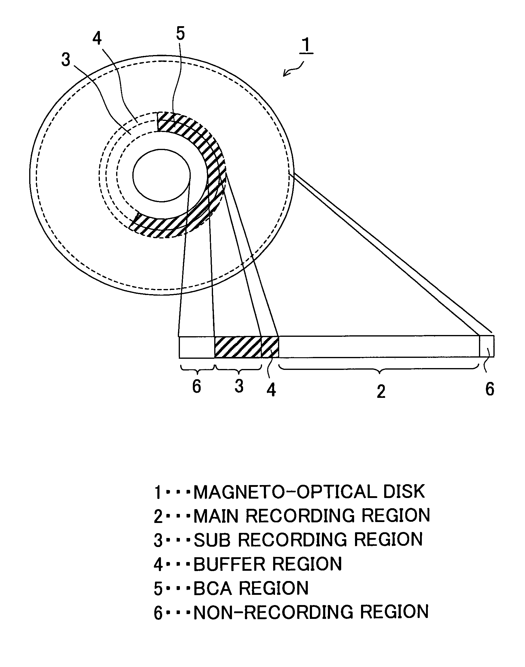
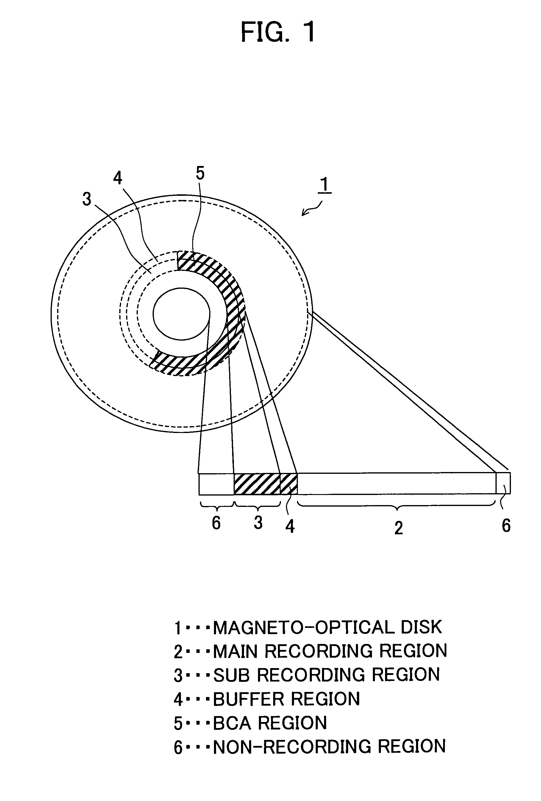
[0071]Below, preferred embodiments of the magneto-optical disk of the present invention and the method of recording and reproducing using it will be described with reference to the accompanying drawings.

[0072]The magneto-optical disk of the present embodiment is a disk having a small-sized diameter suitable for portable mobile electronic device applications. It has a transparent substrate having a diameter of 64 mm and a thickness of 1.2 mm in the same way as a MiniDisc (MD).

[0073]In the magneto-optical disk of the present embodiment, the magnetically induced super resolution (MSR) reproduction system enabling large capacity recording is employed. According to the magneto-optical disk of the present embodiment, recording and reproduction of a moving picture also become possible. The magneto-optical disk of the present embodiment can be used in a recording and reproducing apparatus having an optical system having a wavelength of 780 nm and a numerical aperture (NA) of 0.45. Compatibi...


PUM


Abstract

A magneto-optical disk having a small-sized diameter and a large capacity and able to record and reproduce disk discrimination information, and a recording method and a reproducing method of the same, wherein a recording layer including a main recording region in which a first information is recorded, a sub recording region in which a second information including the disk discrimination information is recorded, and a buffer region formed between the main recording region and the sub recording region and in which a third information is recorded is provided on a substrate, the second information is recorded by a mark array formed in stripe shapes in the sub recording region and the buffer region, a plurality of marks constituting the mark array are obtained by changing the magnetization state of the recording layer, and the third information is reproduced by a modulation signal of a reflection ratio along a circumferential direction of the disk.

Description

RELATED APPLICATION DATA[0001]The present application claims priority to Japanese Application(s) No(s). P2003-117026filed Apr. 22, 2003, which application(s) is / are incorporated herein by reference to the extent permitted by law.BACKGROUND OF THE INVENTION[0002]1. Field of the Invention[0003]The present invention relates to a magneto-optical disk, a recording method for recording information on a magneto-optical disk, and an information reproducing method for reproducing information from a magneto-optical disk.[0004]The recording method and the reproducing method will be referred to overall as a recording and / or reproduction method.[0005]2. Description of the Related Art[0006]In recent years, along with the increase in volume of information, the recording capacity of optical disks has risen and great advancements have been made in digital information processing technology. In digital versatile disks (DVDs), MPEG2 compression technique has been employed—making it possible to record t...

Claims


Application Information

Patent Timeline
IPC IPC(8): G11B11/00G11B7/004G11B7/005G11B7/007G11B7/24097G11B11/105G11B19/12G11B20/00G11B20/10
CPCG11B20/00268G11B11/10597G11B19/122G11B20/00086G11B11/10528G11B7/00736G11B7/24082G11B7/24094G11B11/10515G11B11/10584G11B11/105
Inventor WATANABE, MAKOTOMIYATA, KAZUTOMOOTA, TERUYUKITOBITA, MINORU
Owner SONY CORP
Learn More