
Method providing distribution means for reference clocks across packetized networks

Active Publication Date: 2008-04-08
ZARLINK SEMICON LTD
View PDF21 Cites 14 Cited by
  • Summary
  • Abstract
  • Description
  • Claims
  • Application Information

AI Technical Summary

Benefits of technology

[0004]Disclosed is a method to distribute a number of reference clocks across a packet network. The described method uses a single “basis clock” per node; this basis clock is synchronized in each of the slave nodes to a master node. The master node also numerically encodes a number of reference clocks with respect to the master's basis clock. At each slave node, with the slave node's basis clock synchronized to the master basis clock, and with numerical information describing the reference clock(s) with regard to the master's basis clock, the reference clock(s) can be reconstructed with high accuracy.
[0007]There are many advantages in using the disclosed method. The method works on existing networks without proprietary modifications to the hubs, switches and routers. It is possible to efficiently encode multiple reference clocks with the possibility of using minimum bandwidth per reference clock. In addition, it offers better wander performance than Adaptive Clock Recovery methods, when multiple reference clocks are present. Such a situation may arise when a number of T1 or E1 lines come into the source node, each having its own primary reference clock.

Problems solved by technology

This is not a good match for some services which formerly ran over plesiochronous TDM network connections, where each connection was allowed a certain frequency inaccuracy, hence multiple connections entailed multiple reference clocks.
Adaptive clock recovery tends to have poor wander performance, even when timestamping and packet sequence numbering are used to overcome packet-loss issues.

Method used


Image

  • Method providing distribution means for reference clocks across packetized networks
  • Method providing distribution means for reference clocks across packetized networks
  • Method providing distribution means for reference clocks across packetized networks

Examples


Embodiment Construction

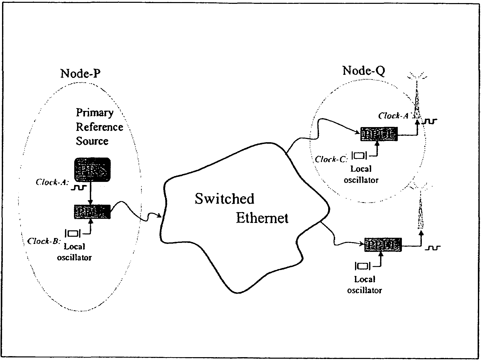
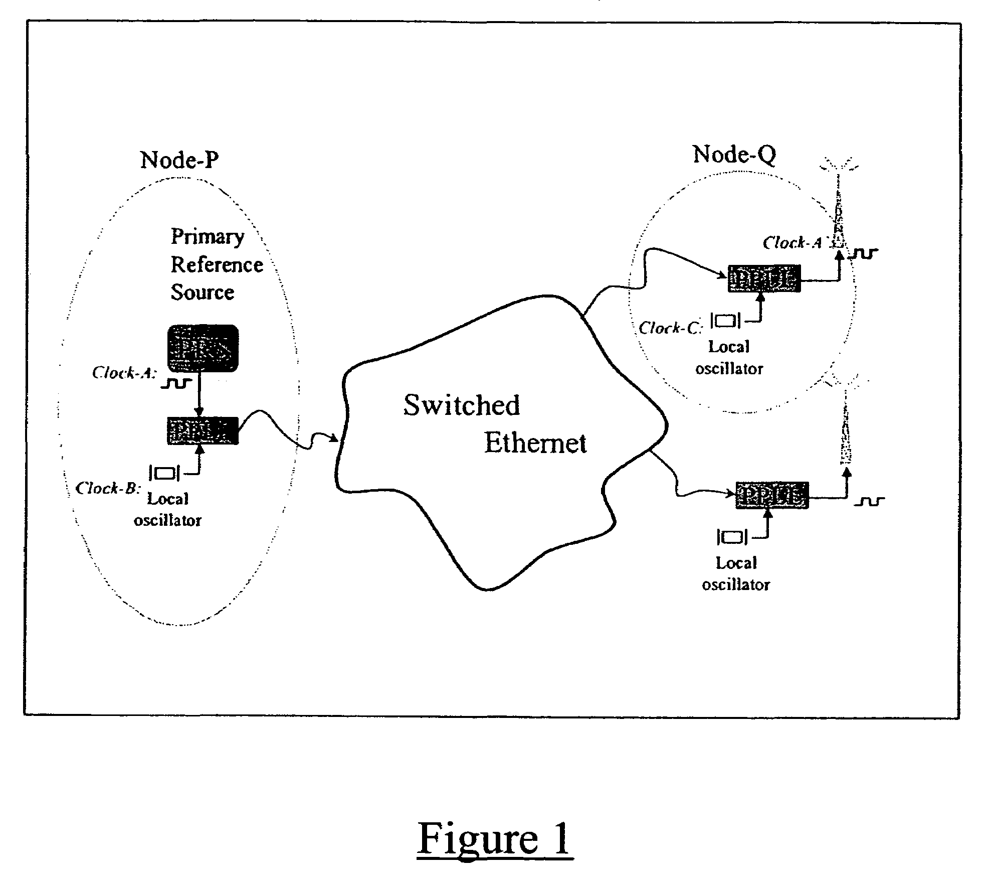
[0013]FIG. 1 shows a simple configuration with two slave nodes and a single reference clock. The local oscillator which is the basis clock for slave node Q is characterized against the local oscillator which is the basis clock for master node P. These local oscillators offer one place to perform a cost / benefit tradeoff—better, more expensive oscillators provide better performance.

[0014]FIG. 1 shows one reference clock “Clock A”. A series of alignment calculations is performed.

[0015]Alignment 1: Reference Clock Versus Master DCO

[0016]The DCO in the PPLL block at the master node will be locked to the incoming reference Clock A in a standard manner for digital PLLs: A PI-controller will lock the master DCO (acquisition PLL) to the reference clock.

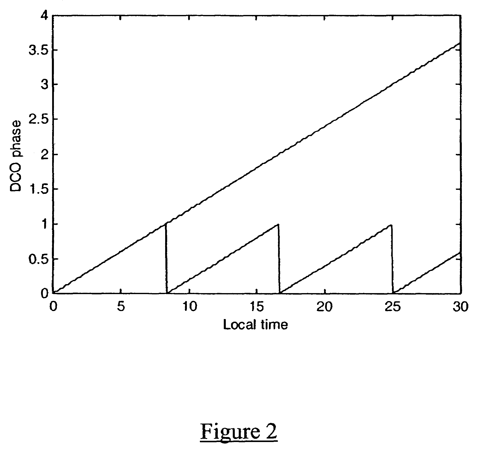
[0017]Alignment 2: Master DCO Versus Master Local Time

[0018]The DCO ramp of the master describes a saw tooth as a function of its local time and represents unambiguously both phase and frequency of the reference clock (FIG. 2).

[0019]In the P-P...


PUM


Abstract

Disclosed is a method of distributing a number of reference clocks across a packet network. The packet network has a master node and one or more slave nodes, the master node and each slave node having basis clocks. A sender sends time-stamped synchronization packets to said one or more slave nodes, and a receiver at the slave nodes receives the time-stamped synchronization packets and synchronizes the basis clocks in the slave nodes with the basis clock in the master node. Multiple reference clocks are encoded with respect to the basis clock in the master node to generate numerical information describing the reference clock(s) in relation to the basis clock in the master node. The basis clock in each of the slave node is synchronized to the basis clock in the master node using time-stamped synchronization packets. The one or more reference clocks are recovered at the slave nodes using said numerical information describing the reference clock(s) in relation to the basis clock in the master node.

Description

CROSS-REFERENCE TO RELATED APPLICATION[0001]This application claims the benefit under 35 U.S.C. 119(e) of U.S. Provisional Application No. 60 / 448,738 filed Feb. 20, 2003, the contents of which are incorporated by reference herein.FIELD OF THE INVENTION[0002]The present invention relates to the field of digital communications. More specifically, the present invention relates to a method of distributing fine-grained clocks across packet networks.BACKGROUND OF THE INVENTION[0003]There is increasing interest in providing telecommunications services over packet networks that were formerly provided over TDM (time division multiplexed) networks. Most of these telecommunications services require a synchronized clock, which is not provided by the physical layer of a packet network in the same way as it was provided by the physical layer of the TDM network. Various approaches to synchronization over packet networks have been proposed and standardized (see NTP and IEEE Std 1588, among others),...

Claims


Application Information

Patent Timeline
IPC IPC(8): H04L12/28G06F1/12H04L7/00H04J3/06H04L12/56
CPCH04J3/0664H04J3/0641H04J3/06H04L5/00H04L7/033H04L2012/5603
Inventor VAN DER VALK, ROBERTUS LAURENTIUSREPKO, WILLEM L.
Owner ZARLINK SEMICON LTD
Learn More