Compression screw with combination single and double flights

a compression screw and double-flying technology, applied in the field of dewatering, can solve the problems of single-flying screw inherent unbalanced load, bulk materials having a consistency greater than 25 percent, and difficult dewatering of bulk materials, etc., and achieve the effect of high cr, beneficial pressure wave, and high compression ratio problem

Active Publication Date: 2008-04-15
ANDRITZ INC
View PDF6 Cites 32 Cited by
  • Summary
  • Abstract
  • Description
  • Claims
  • Application Information

AI Technical Summary

Benefits of technology

[0012]The significantly improved dewatering effectiveness of the invention is likely attributable to the synergy achieved by combining the best attributes of a single flight screw with the best attributes of a dual flight screw, while assuring an effective transition between them. A single flight would produce an unbalanced radial pressure wave (viewing the dewatering section in an axial cross section). The unbalanced wave forces the screw into an orbit as opposed to staying centered within the housing. As the compression ratio is increased on the single flight screw, power is consumed in deflection and orbit of the screw, at the expense of processing of material. A double flight has a balanced pressure wave and thus no orbit from deflection. The ability to handle the increased compression ratio results in a direct process benefit relative to single flight screws. However, a number of inexplicable feed forward problems can arise, particularly production rate variation, production loss, output consistency variation, and reduction of plug holding (pressure seal) capacity. The root cause of this is not obvious, but through significant insights the present inventors now realize that the problem was rotation of material in the inlet section of the device.
[0013]The hybrid single / double flight design of the present invention inherently solves the feed forward problem and the high compression ratio problem. In the inlet zone, a single flight accepts feed material deposited by gravity, and conveys the material axially forward. In the compression zone a double flight achieves high CR without deverting the energy into deflection and orbiting of the shaft. A flightless transition section, evenly distributes the material to the dual flight section, and also imparts a beneficial pressure wave.

Problems solved by technology

Dewatering of bulk solid materials has been particularly difficult.
Whereas dewatering of pulp slurries having a consistency in the range of 4-5 percent is relatively easy, dewatering of bulk materials having a consistency greater than 25 percent, has posed problems.
These problems arise from the difficulties in managing the relative friction among the screw shaft, screw flights, and compression housing wall.
It is also known that when very high compression ratios are desired, single flight screws have inherent unbalanced loads and reach a point of diminishing returns whereby a given increment of applied energy (in the form of increased torque on the screw) produces very little benefit in the way of further dewatering.

Method used


Image

  • Compression screw with combination single and double flights
  • Compression screw with combination single and double flights
  • Compression screw with combination single and double flights

Examples


Embodiment Construction

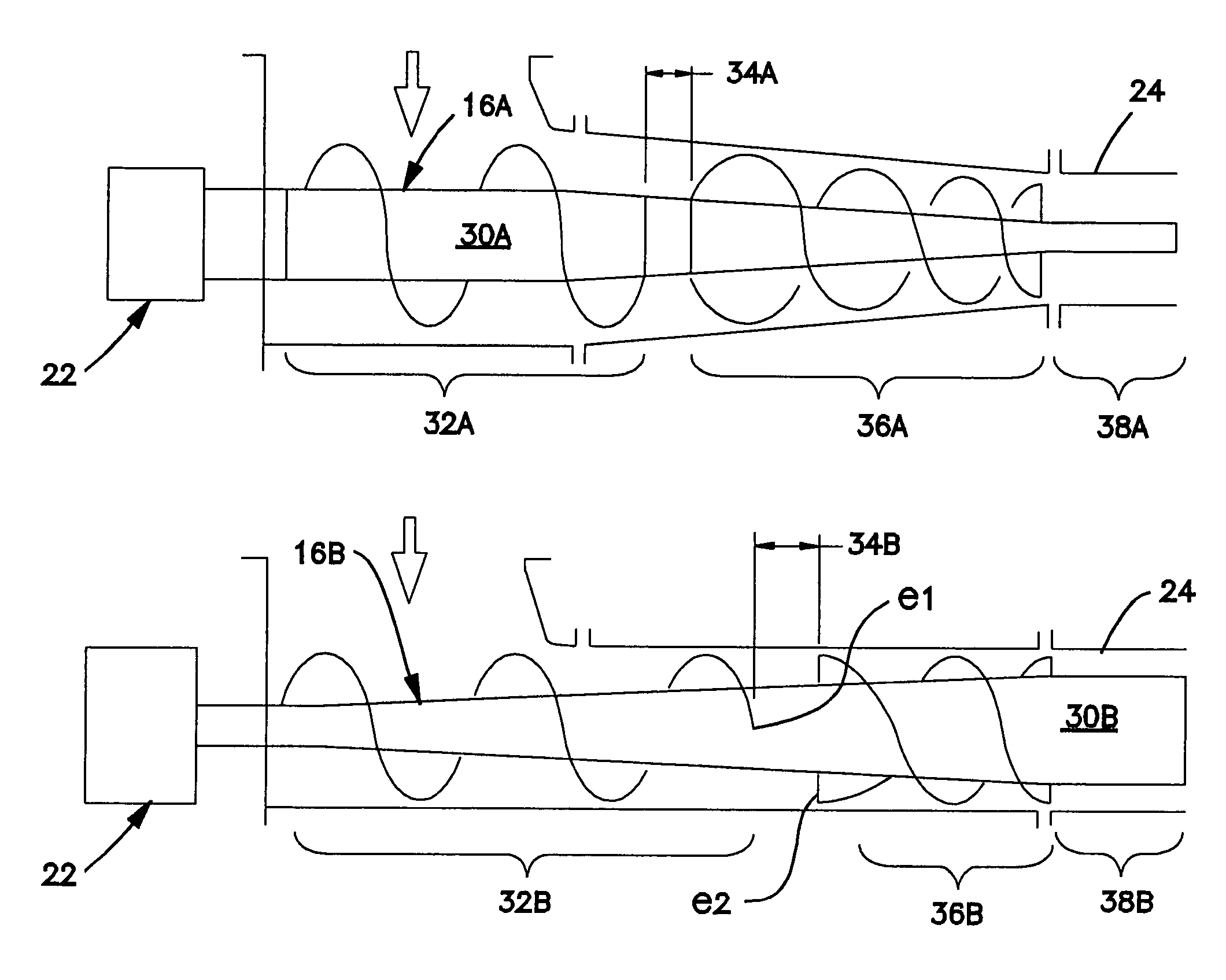
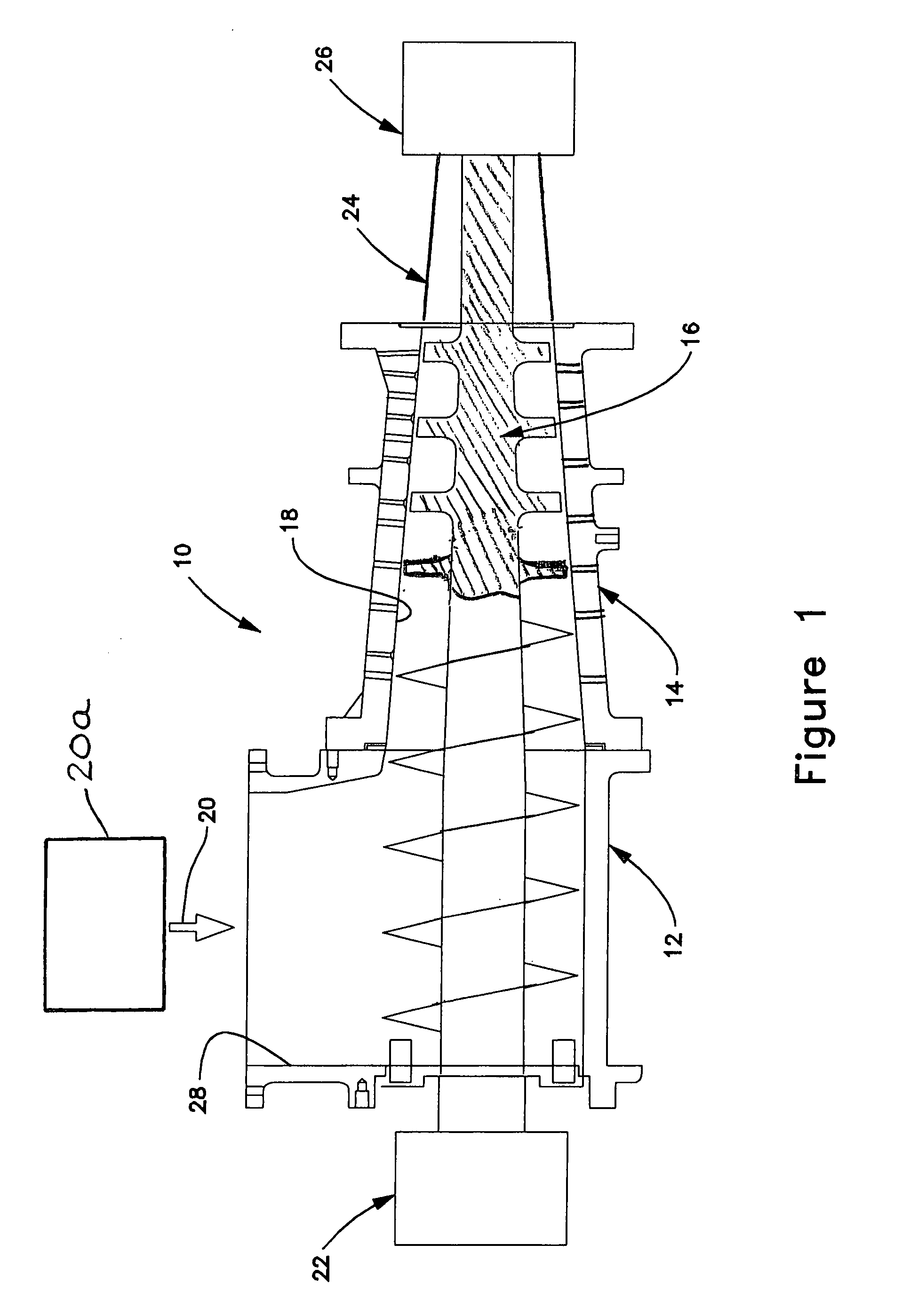
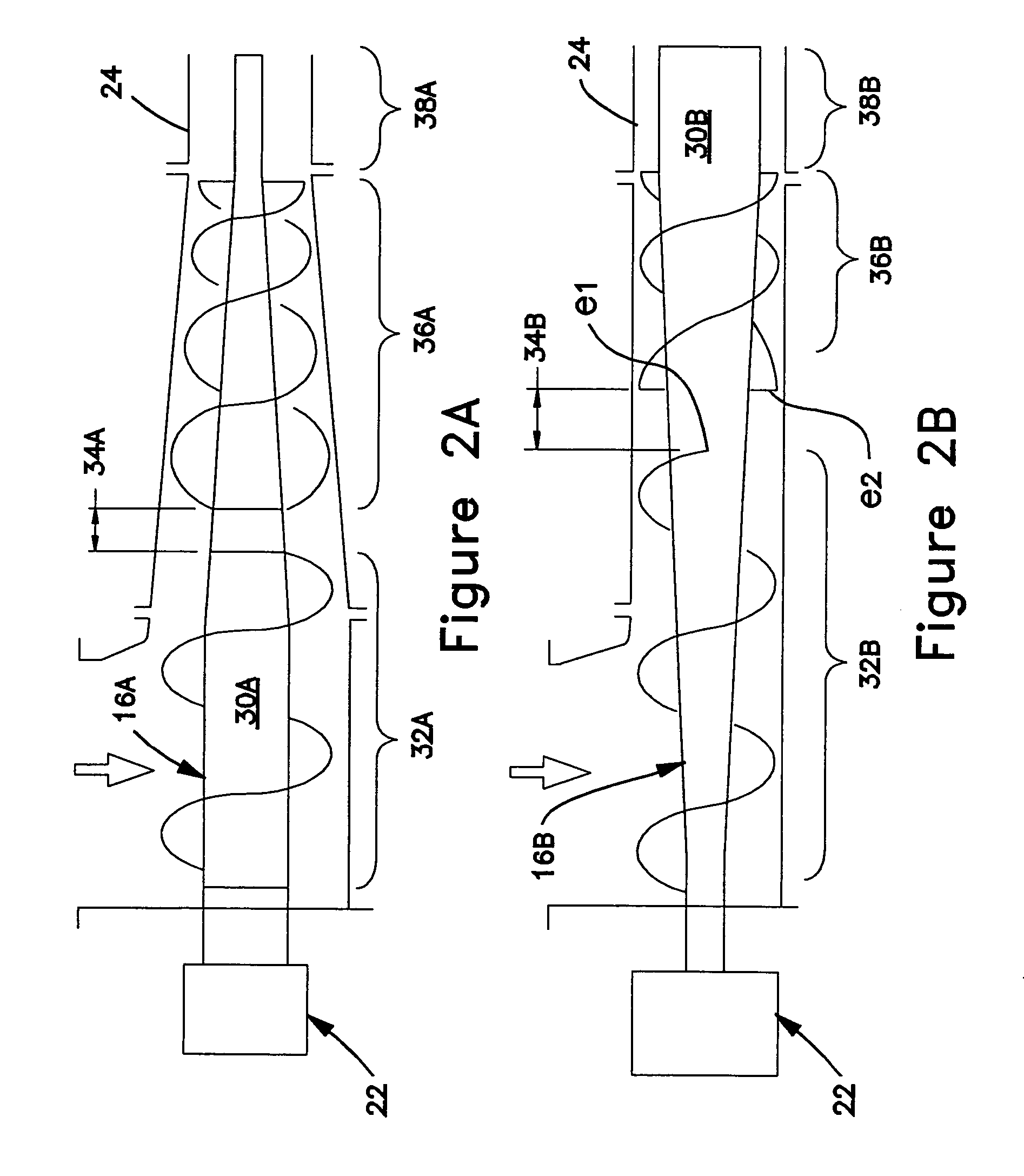
[0020]FIG. 1 is a partially sectioned longitudinal view of the dewatering device 10 with associated components in accordance with one embodiment of the invention. The dewatering device 10 comprises one, two, three, or more physical housing sections that are rigidly connected together end-to-end to form a substantially tubular housing. For example, a feed section 12 forms a hopper, which is followed by a compression section 14. The feed section is sometimes perforated to allow free water to drain, but is not active for compression drainage. Functionally, feed material is received in the feed zone of the hopper and conveyed to the dewatering zone of the compression section. The functional zones are defined primarily by the relationship between a central screw 16 and the inside wall 18 of the surrounding housing. The screw has inlet and discharge ends mounted for rotation within the housing.

[0021]The conveying or feed section at the inlet end of the screw receives feed material deposit...


PUM

PropertyMeasurementUnit
axial lengthaaaaaaaaaa
lengthaaaaaaaaaa
axial lengthaaaaaaaaaa

Abstract

A screw for a compression dewatering device comprising an elongated shaft having axially spaced apart first and second ends, a conveying section at the first end of the shaft, having a single helical screw flight rigidly projecting from the shaft, a flightless transition section axially adjacent the conveying section, and a dewatering section axially adjacent the transition section, having a double helical screw flight rigidly projecting from the shaft. Another embodiment is a compression screw with similar characteristics having a perforated tubular dewatering wall intermediate the ends, followed by an imperforate spool wall at the discharge end. A gravity feed device is operatively associated with the inlet end of the screw shaft for depositing bulk solids material through the feed opening onto the conveying screw, and a drive system is operatively connected to the inlet end of the screw for rotating the screw in the housing.

Description

RELATED APPLICATION[0001]This application claims the benefit under 35 U.S.C. Sec. 119(e), of the filing date of U.S. Provisional Application No. 60 / 658,250 filed Mar. 2, 2005, for “Compression Screw With Combination Single and Double Flights”.BACKGROUND OF THE INVENTION[0002]The present invention relates to the dewatering of wood byproducts to produce a furnish for a mechanical refiner or chemical digester, for conversion of fibers into pulp.[0003]The purpose of a dewatering compression screw device in the overall processes of greatest interest, production of fiberboard (MDF), particleboard (PB), or thermomechanical pulp (TMP), is to remove fluids (extractives) from the raw material and form a pressure plug prior to entry of the dewatered material into the digester or refiner. The raw material is typically sawdust, wood shavings, or wood chips, which are generally considered bulk solids. No pre-processing is required before dewatering, except for washing or pre-steaming. In MDF or P...

Claims


Application Information

Patent Timeline
Patent Type & Authority Patents(United States)
IPC IPC(8): B30B9/14
CPCB30B9/121B30B9/122B30B9/26
Inventor KRAFT, MICHAEL J.KELLER, JOSEPH L.RIOTTO, ANTHONY M.
Owner ANDRITZ INC
Why Eureka
Try Eureka