
System for efficiently cooling a processor

a processor and efficient technology, applied in the field of computer hardware, can solve the problems of consuming a large amount of power, increasing noise, and annoyance of people, and achieve the effects of less airflow noise during operation, less noise, and reliable operation

Active Publication Date: 2008-04-15
NVIDIA CORP
View PDF13 Cites 27 Cited by
  • Summary
  • Abstract
  • Description
  • Claims
  • Application Information

AI Technical Summary

Benefits of technology

The system reduces airflow noise, increases reliability, and enhances heat dissipation efficiency, extending pump life and reducing maintenance needs while achieving lower processor temperatures with reduced power consumption.

Problems solved by technology

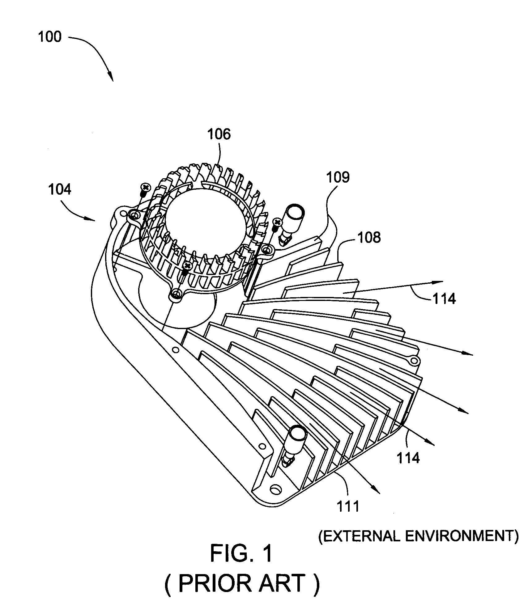
One drawback of using system 100 to cool a processor is that a sound wave produced when fan 106 forces air through an air channel 108 oftentimes establishes a standing wave within air channel 108.
The increased noise is particularly annoying to persons who use computers and other electronic devices that include a system similar to system 100.
However, typical fluid cooling systems are driven by large pumps, which are prone to frequent failure and tend to consume a great deal of power.
Moreover, such systems tend to use large quantities of fluid, circulating at a high flow rate, and therefore must be frequently replenished or replaced.

Method used


Image

  • System for efficiently cooling a processor
  • System for efficiently cooling a processor
  • System for efficiently cooling a processor

Examples


Embodiment Construction

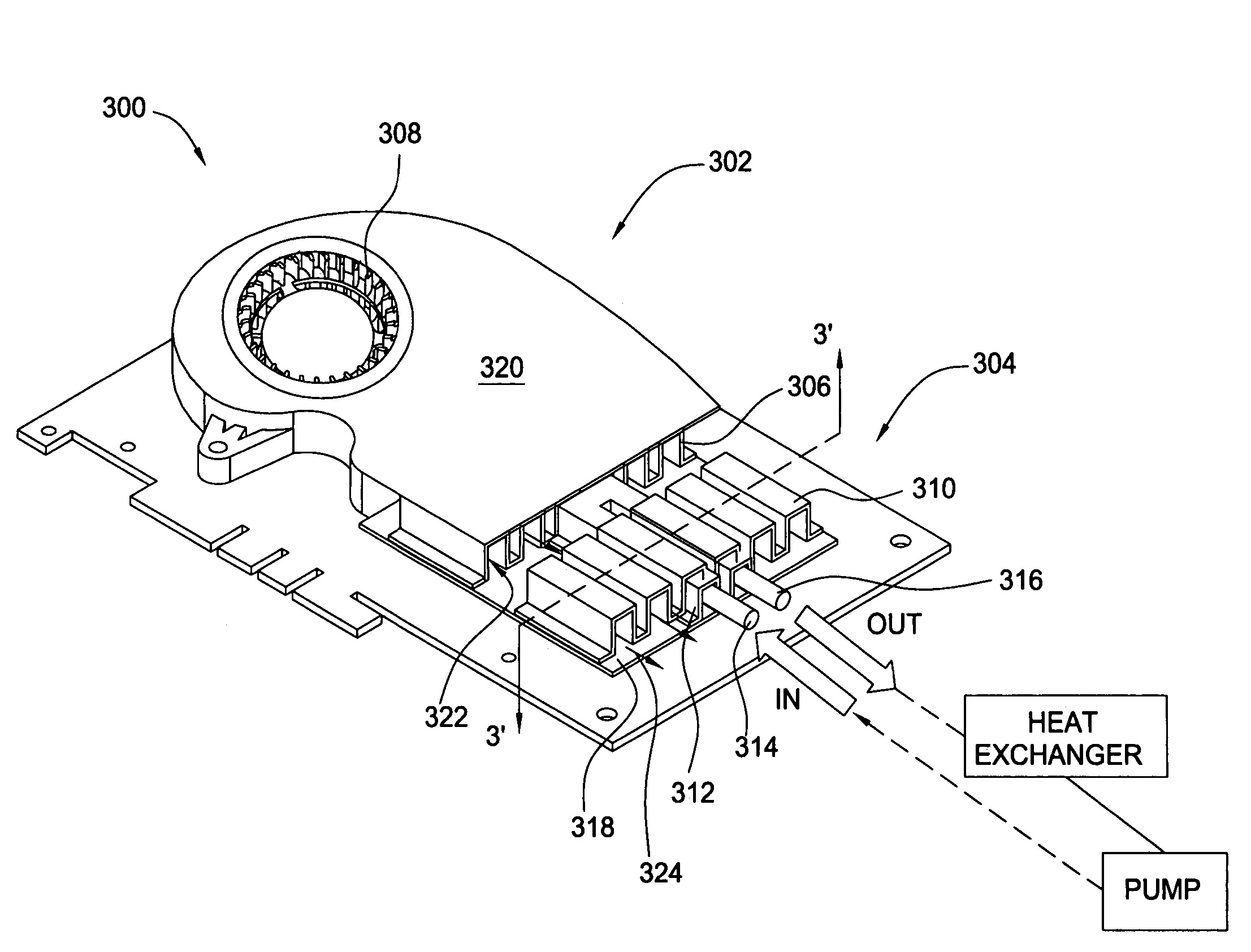
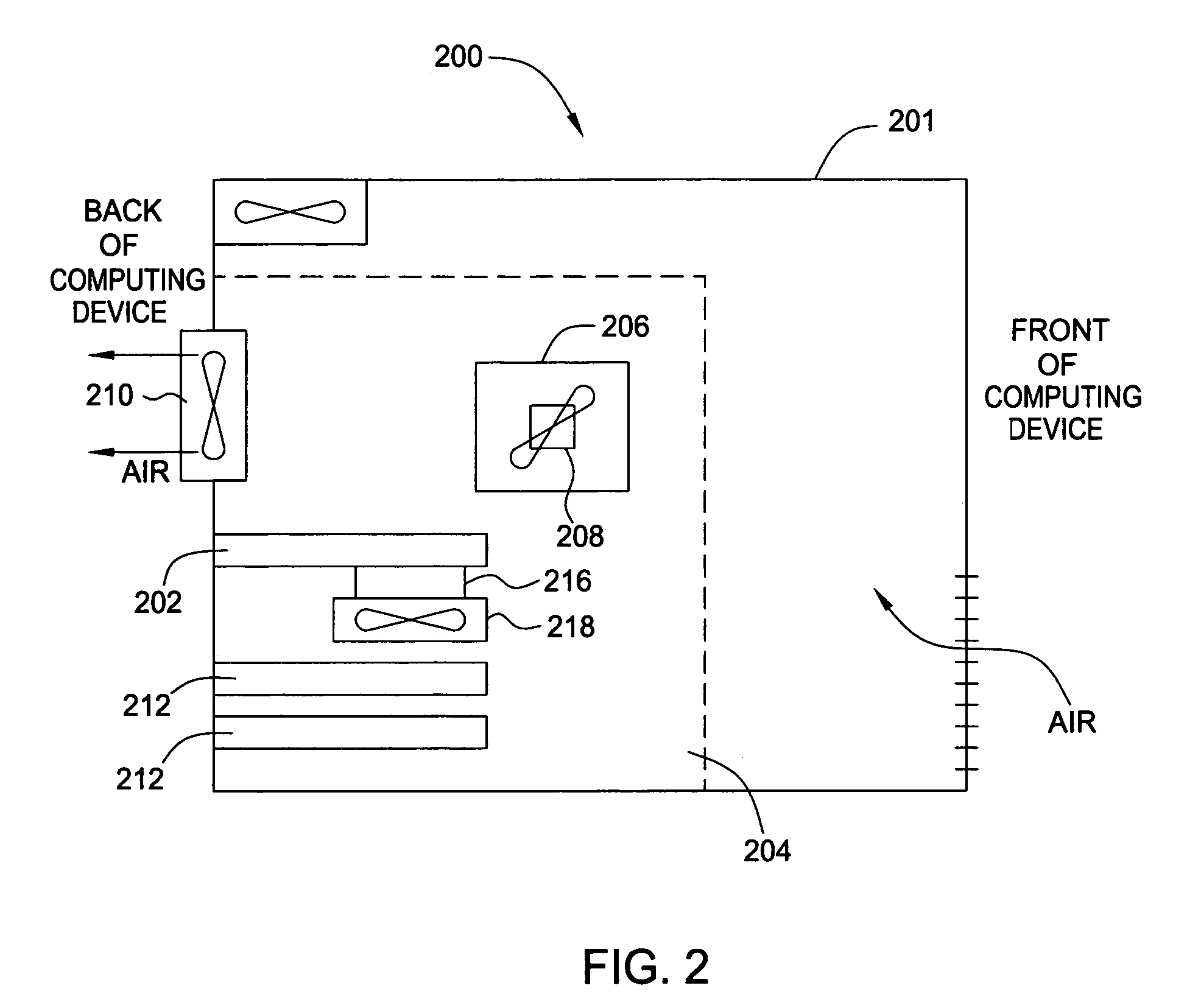
[0019]FIG. 2 is schematic diagram illustrating a computing device 200 adapted for use with a system 218 for cooling a processor, according to one embodiment of the present invention. Computing device 200 may be any type of computing device, including, without limitation, a desktop computer, a server, a laptop computer, a palm-sized computer, a personal digital assistant (PDA), a tablet computer, a gaming console, a cellular telephone, a computer-based simulator and the like.

[0020]As shown, computing device 200 includes a housing 201, within which a motherboard 204 resides. Mounted on motherboard 204 are a central processing unit (CPU) 206, a processor cooler 208 for cooling CPU 206, a system fan 210 for removing heat from computing device 200, and one or more peripheral component interface (PCI) cards 212, each interfaced with a slot located in the back part of housing 201. Motherboard 204 further incorporates a graphics card 202 that enables computing device 200 to rapidly process ...


PUM


Abstract

One embodiment of a system for efficiently cooling a processor includes an active hybrid heat transport module adapted to be integrated with a fansink. The hybrid heat transport module comprises both a fluid channel and an air channel adapted for transporting heat. The hybrid heat transport module and the fansink may be used alone or in combination to dissipate heat from the processor.

Description

BACKGROUND OF THE INVENTION[0001]1. Field of the Invention[0002]This invention relates generally to computer hardware and more particularly to a system for efficiently cooling a processor.[0003]2. Description of the Background Art[0004]FIG. 1 is an isometric view illustrating a prior art system 100 used to cool a processor (not shown). As shown, system 100 characteristically includes a heat sink assembly 104, which further includes a fan 106, walls 109 and a bottom plate 111. Typically, system 100 is thermally coupled to a processor, for example using thermal adhesive having thermal properties that facilitate transferring heat generated by the processor to bottom plate 111 of heat sink assembly 104. System 100 may also include a heat sink lid (not shown), which, among other things, prevents particles and other contaminants from entering fan 106 and air blown from fan 106 from escaping system 100. Heat sink lid 102, together with walls 109 and bottom plate 111 of heat sink assembly 1...

Claims


Application Information

Patent Timeline
Patent Type & Authority Patents(United States)
IPC IPC(8): H05K7/20G06F1/20
CPCG06F1/20H05K7/20772H05K7/20727G06F2200/201
Inventor STEFANOSKI, ZORANKIM, JEONG H.
Owner NVIDIA CORP
Learn More