
Method and system for providing end-to-end security solutions to aid protocol acceleration over networks using selective layer encryption

Inactive Publication Date: 2008-04-15
RAGIREDDY KRISHNA +2
View PDF8 Cites 145 Cited by
  • Summary
  • Abstract
  • Description
  • Claims
  • Application Information

AI Technical Summary

Benefits of technology

[0020]Accordingly, there exists a significant need for a ful

Problems solved by technology

Also, all transmission equipment introduce additional delay, called latency.
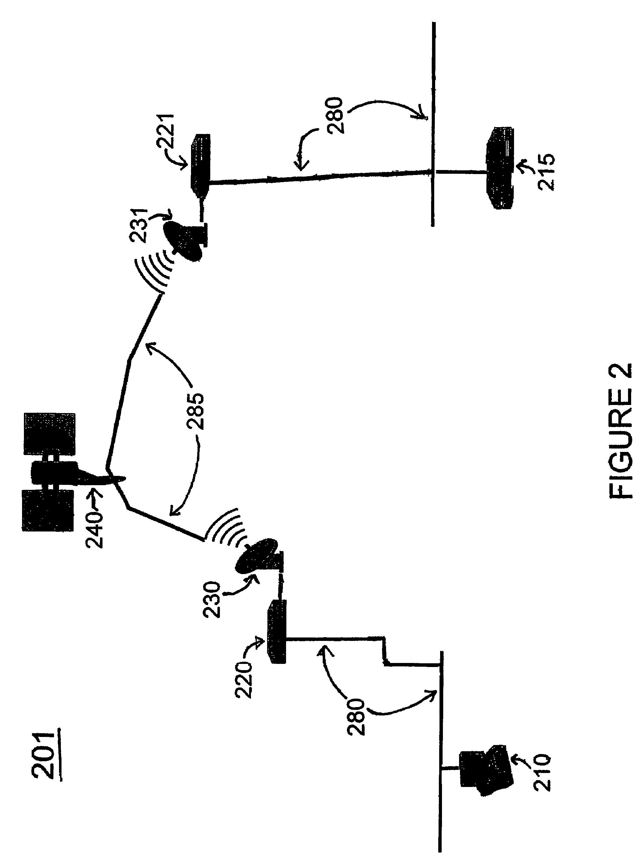
For example, although satellite networks have advantages such as permitting telecommunication across any distance without laying ground lines, the distance between the ground and the satellite introduces significant transmission delay.
As another example, cellular wireless networks contain many packet switches, each of which introduces some latency; the cumulative delay can exceed that of a satellite link.
As a result of the distance traveled by transmissions from one node (e.g., a ground station) to another node via a satellite, significant transmission delays may be incurred.
Such delay causes certain performance issues for voice applications.
For example, problems such as “conversation collisions” occur wherein both parties start talking at the same time because neither can hear that the other party is also talking.
Data protocols within satellite and other high-latency networks also face problems with long delays.
Two problems in particular handicap the use of satellite networks for data applications: throughput limitation and partial security.
Throughput limitation refers to the fact that Transmission Control Protocol (TCP) sending devices (among many devices that transmit data packets) cannot transmit at rates in excess of the rates at which the receiver device can acknowledge receipt of the packets.
However, in a satellite network, the inherent delay caused by long-distance transmission results in each sending TCP device being required to wait idle for each acknowledgement.
In practice, this forced wait limits the average transmission speed to approximately 130 kbit / s, regardless of the channel bandwidth of the satellite transmission.
An additional problem is that a TCP device may misinterpret the inherently long delay as network congestion.
This algorithm implemented by TCP further reduces the efficiency of a channel impaired by high latency.
A second drawback in using satellite communication is low security.
However, hub earth stations are seldom at customer sites and so there will likely exist a terrestrial segment that is not protected by the satellite service provider.
Prior art solutions for each problem (i.e., throughput limitation and low security) do exist, but each have their own respective drawbacks.
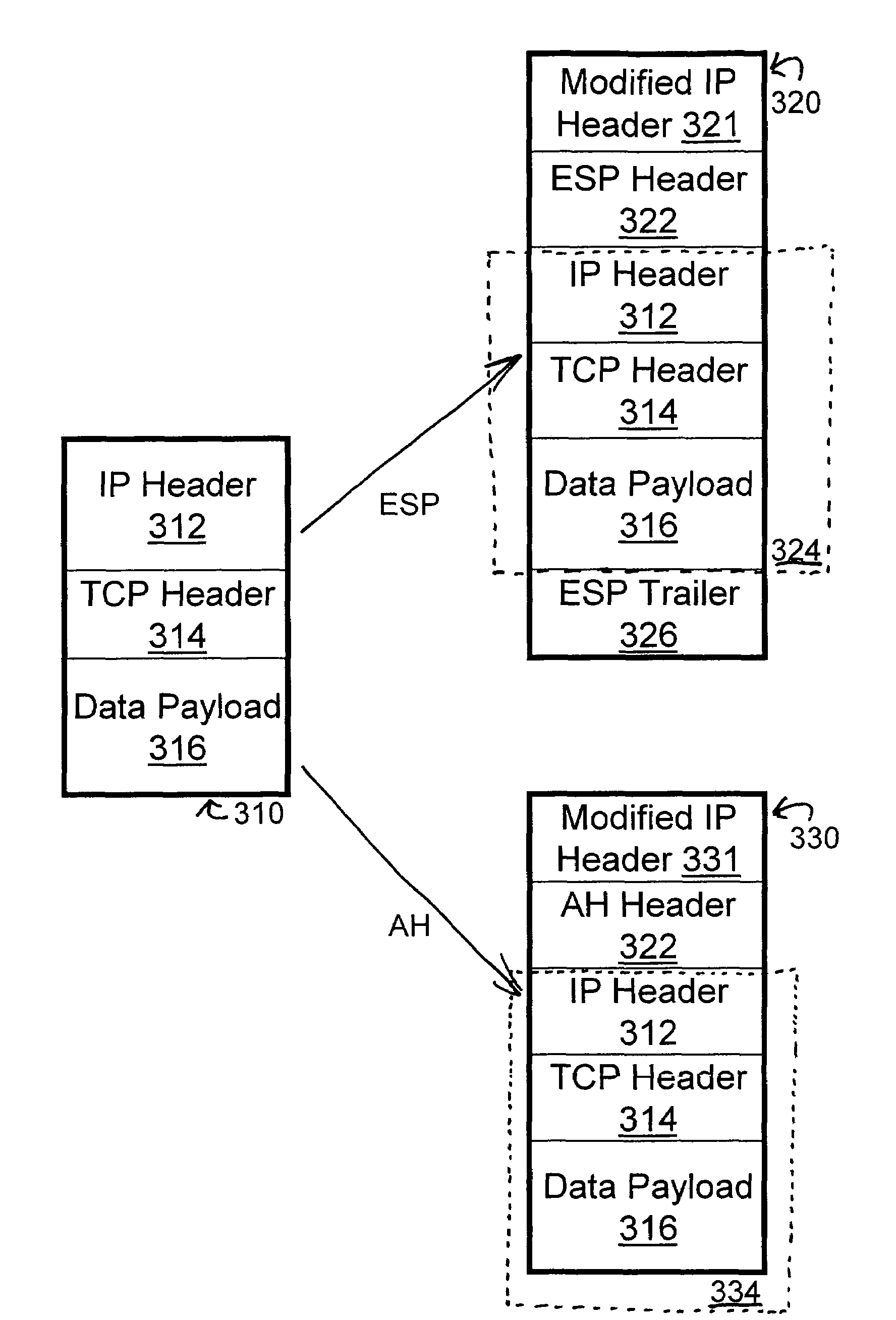
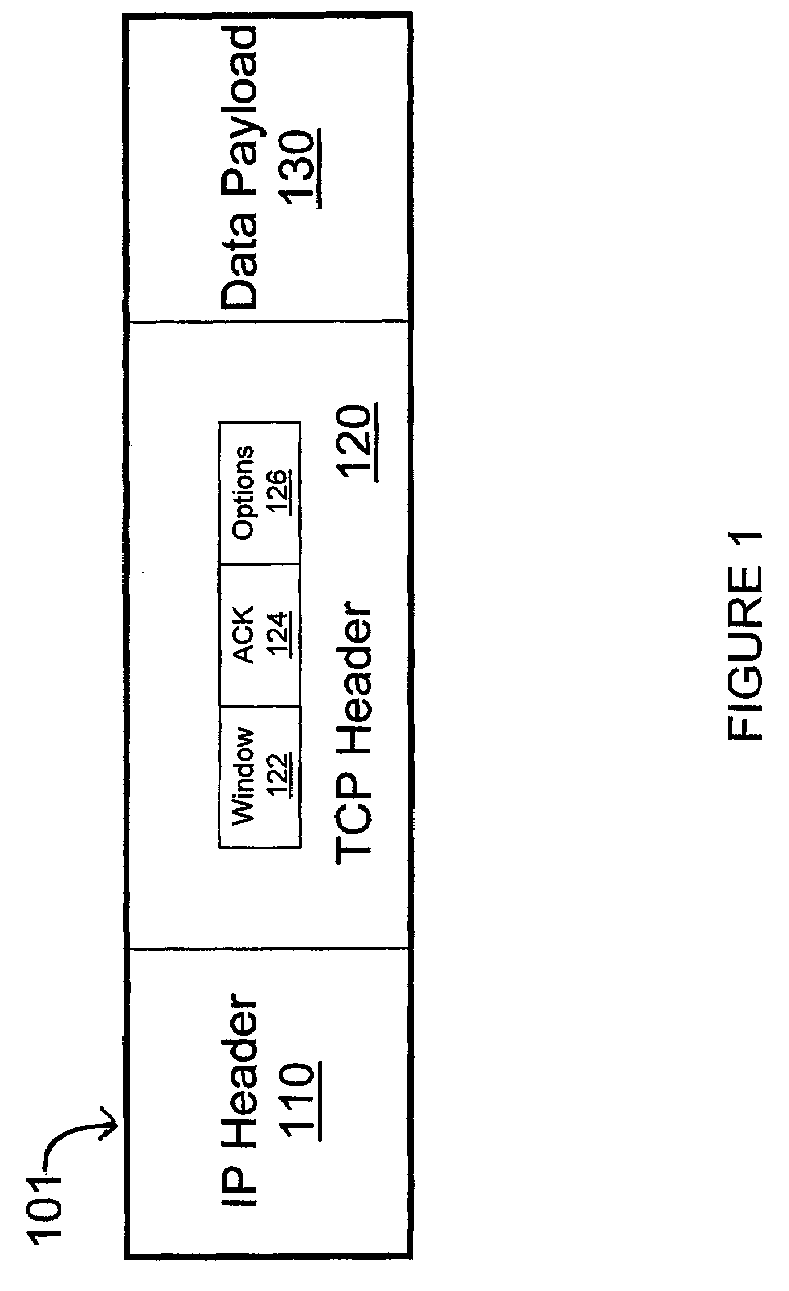
This total encryption, however prevents the PEP device from seeing or modifying the original TCP header 314 (specifically, the ACK and Window fields of the header), so these sessions cannot be accelerated by PEP devices.
Any change in the protected TCP header (like those changes made by PEP devices) will result in a failure of the authentication process and a rejection of the protected packet.
The result is that a PEP device that has just decrypted data will send unencrypted data to an IPsec router.
Even though the IPsec router may be proximate to the PEP device, the existence of an “unencrypted six inches” on the cable between an IPsec router and a PEP is unacceptable to many enterprises and government agencies as they often require complete end-to-end confidentiality.
The result of these problems has been a conflict between maximizing throughput and maximizing high security using IPsec VPNs.
In summary, standard IPsec cannot be accelerated by PEP devices; the additional processing time to encrypt / decrypt (and compress / decompress) further lengthens the ACK cycle, cutting throughput and reducing security.

Method used


Image

  • Method and system for providing end-to-end security solutions to aid protocol acceleration over networks using selective layer encryption
  • Method and system for providing end-to-end security solutions to aid protocol acceleration over networks using selective layer encryption
  • Method and system for providing end-to-end security solutions to aid protocol acceleration over networks using selective layer encryption

Examples


Embodiment Construction

[0039]The present invention is now described in more detail herein in terms of various exemplary embodiments. This is for convenience only and is not intended to limit the application of the present invention. In fact, after reading the following description, it will be apparent to one skilled in the relevant art(s) how to implement the following invention in alternative embodiments. Moreover, the present invention can be implemented using software, hardware or any combination thereof as is known to one of ordinary skill in the art.

[0040]The present invention meets the above-identified needs for simultaneous high throughput and encryption by providing a system, method, and computer program product for Selective Layer Encryption (SLE) within all networks that experience some degree of latency. Such networks can include, but are not limited to satellite communications, cellular data service, terrestrial networks that experience some degree of signal latency such as the Internet, a rad...


PUM


Abstract

The present invention is a method, system, and computer program that provides secure network communication over a network between a first and a second entity wherein data packets are encrypted and transmitted according to previously exchanged encryption command information and wherein TCP accelerators may be used to effectively accelerate the transmission of the data packets. A method, system, and computer program are also shown that provide secure network communication through encrypting a plurality of payloads and embedding encryption command information for each encrypted payload into an options field of a corresponding protocol header while still allowing TCP accelerators to read the protocol headers and effectively accelerate the transmission of the payloads.

Description

CROSS-REFERENCE TO RELATED APPLICATION[0001]This application claims the benefit of U.S. Provisional Application No. 60 / 547,587, entitled METHOD FOR PROVIDING END-TO-END SECURITY SOLUTIONS OVER SATELLITE NETWORKS USING SELECTIVE LAYER ENCRYPTION, filed Feb. 26, 2004, the entire disclosure of which is incorporated herein by reference.FIELD OF THE INVENTION[0002]The present invention generally relates to satellite networks and other communications media that display high latency, and more particularly to methods for securing end-to-end virtual private network communication across any such high-latency networks.BACKGROUND OF THE INVENTION[0003]Any transmission medium or network requires a finite time to carry a message from source to destination. The speed of light over a direct path determines the theoretical minimum transmission time. Also, all transmission equipment introduce additional delay, called latency. For example, although satellite networks have advantages such as permitting...

Claims


Application Information

Patent Timeline
IPC IPC(8): H04L29/00
CPCH04L63/0428H04L69/16H04L69/22H04L69/161H04L69/163H04L63/164
Inventor RAGIREDDY, KRISHNAROPER, COLINUHLIG, WILLIAM
Owner RAGIREDDY KRISHNA
Learn More