Encoder alternator

Active Publication Date: 2008-04-22
WOODWARD GOVERNOR CO
View PDF17 Cites 202 Cited by
  • Summary
  • Abstract
  • Description
  • Claims
  • Application Information

AI Technical Summary

Benefits of technology

[0002]Alternators for internal combustion engines are known in the prior art. The alternator is driven by a rotary crankshaft of the engine and supplies electrical power for the engine. Various engine control functions, such as ignition timing, injector timing, etc., require that crankshaft position be known. Typically, in the prior art, angular position of the crankshaft is provided by a reluctor or reluctan

Problems solved by technology

For small, low-cost engines, externally mounted

Method used


Image

  • Encoder alternator
  • Encoder alternator
  • Encoder alternator

Examples


Embodiment Construction

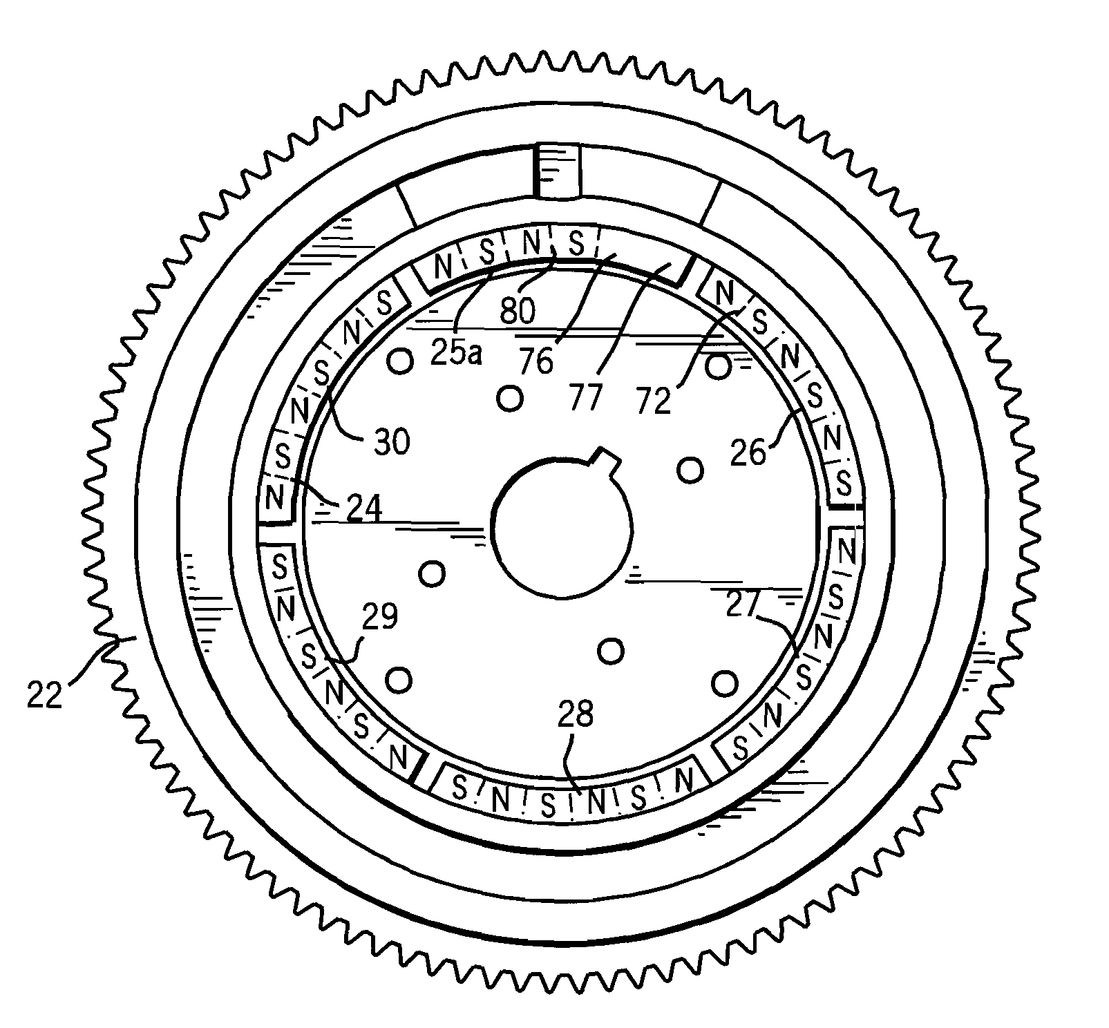
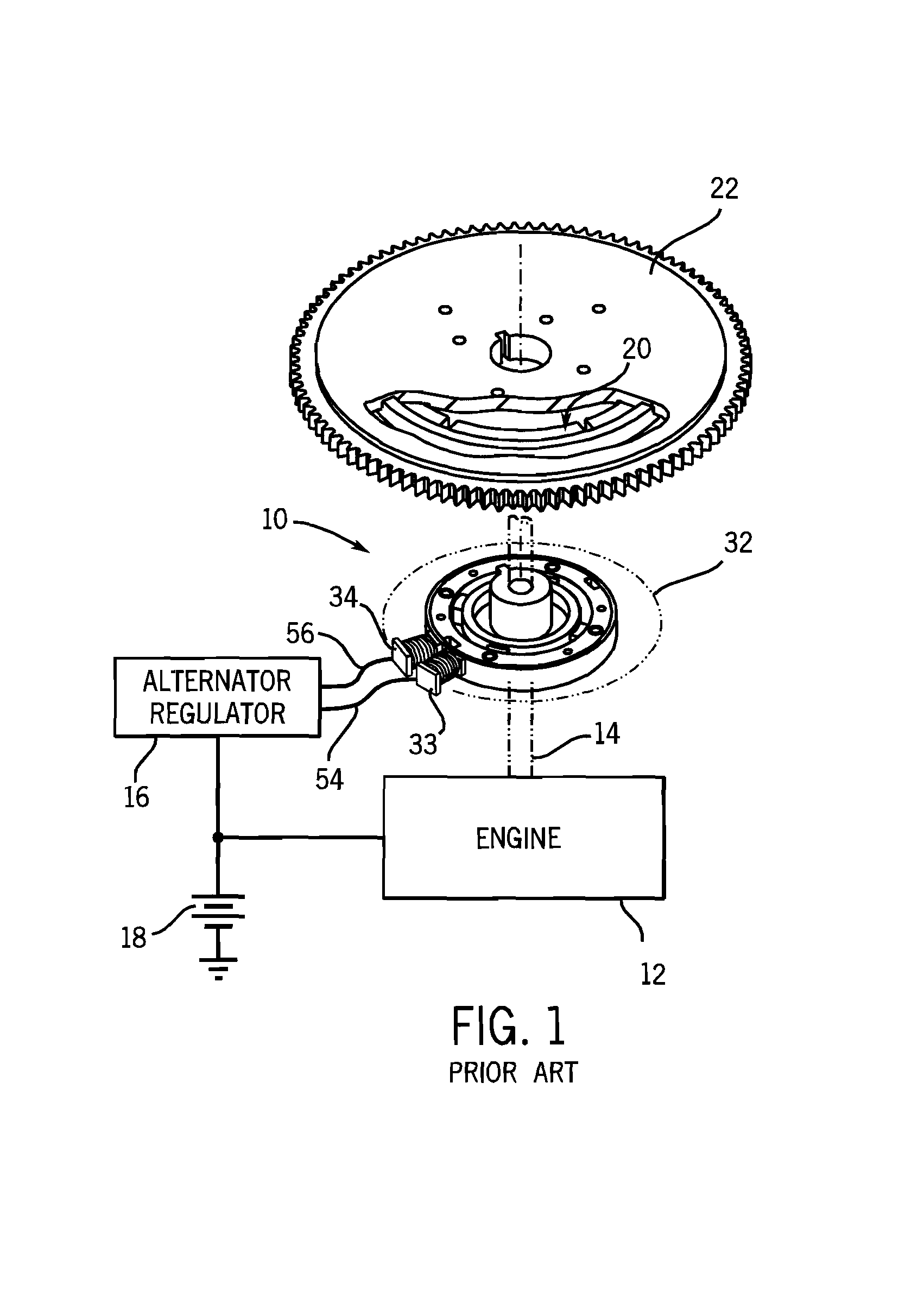
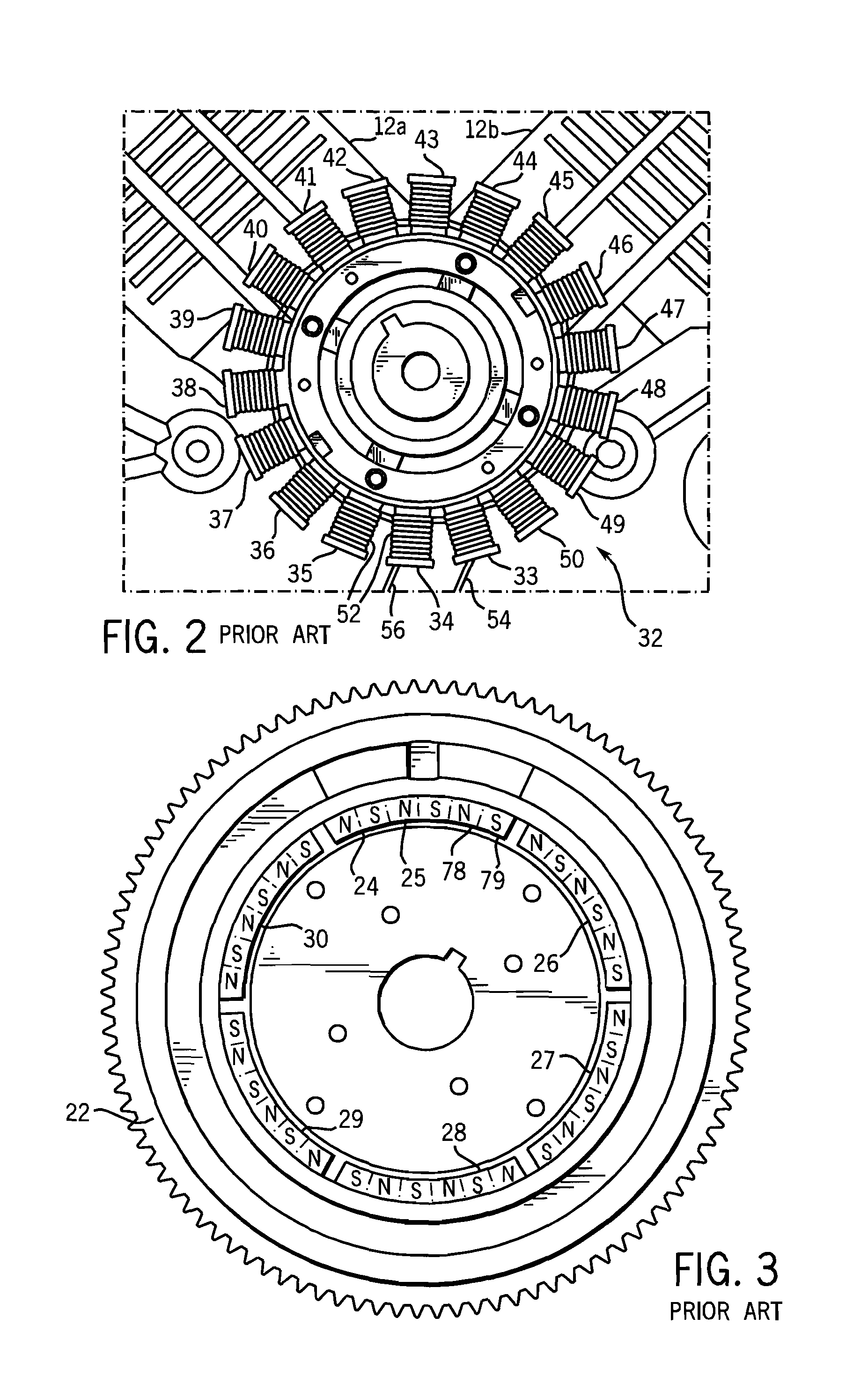
[0011]FIG. 1 shows an alternator 10 for an internal combustion engine 12 having a rotary crankshaft 14. The alternator is driven by the crankshaft and supplies electrical power for the engine, e.g. through an alternator regulator 16 and including for charging battery 18. The alternator includes a permanent magnet rotor 20 mounted for rotation by the crankshaft, e.g. by being mounted to the flywheel 22, and having a plurality of circumferential magnetic rotor poles 24, FIGS. 1, 3, with spaced north-south pole borders in a periodic pattern. For example, in the embodiment of FIG. 3, six arcuate permanent magnets 25, 26, 27, 28, 29, 30 are mounted to flywheel 22, each magnet having three north-south pole pairs. A stator 32 is stationarily mounted to the engine and has a plurality of stator poles, two of which are shown at 33, 34, FIG. 1, for magnetic flux coupling with the permanent magnet rotor poles as flywheel 22 rotates upon rotation of engine crankshaft 14. In the embodiment of FIG...


PUM


Abstract

An encoder alternator for an internal combustion engine has a rotor with a plurality of circumferential magnetic rotor poles in a periodic pattern except for at least one magnetic irregularity. A sensor coil is wound around a stator pole and outputs a crankshaft position sensor signal when the magnet irregularity of the rotor passes the stator pole.

Description

BACKGROUND AND SUMMARY[0001]The invention relates to alternators for internal combustion engines.[0002]Alternators for internal combustion engines are known in the prior art. The alternator is driven by a rotary crankshaft of the engine and supplies electrical power for the engine. Various engine control functions, such as ignition timing, injector timing, etc., require that crankshaft position be known. Typically, in the prior art, angular position of the crankshaft is provided by a reluctor or reluctance wheel, e.g. having ferrous material in an encoder pattern, such as a missing tooth or a given tooth pattern, which passes a magnet or sensor such that the flux or field density changes, i.e. changes the reluctance relationship. The sensor may be a Hall effect sensor, a VR (variable reluctance) sensor, and so on. For small, low-cost engines, externally mounted sensors and encoder wheels are cost prohibitive.[0003]The present invention address and solves the noted need, including pr...

Claims


Application Information

Patent Timeline
IPC IPC(8): H02K11/00H02K7/02
CPCH02K21/222H02K24/00
Inventor KULOGO, TIMOTHY J.KONOPACKI, JEFFERY M.
Owner WOODWARD GOVERNOR CO
Why Eureka
Try Eureka