Low swing current mode logic family

a logic family and low swing current technology, applied in logic circuits using elementary logic circuit components, electrical equipment, electronic switching, etc., can solve the problems of limited battery life, limited circuit sizing, and limited circuit sizing of some transistors, and achieve low power consumption and low variation in power consumption , the effect of high performan

Inactive Publication Date: 2008-04-22
UNIVERSITE CATHOLIQUE DE LOUVAIN
View PDF7 Cites 11 Cited by
  • Summary
  • Abstract
  • Description
  • Claims
  • Application Information

AI Technical Summary

Benefits of technology

[0010]In a third aspect, the present invention provides a smart card comprising a logic circuit according to the present invention. Due to a low variation in power consumption of a logic circuit of the present invention with respect to different inputs at a logic gate, a smart card based on a logic circuit of the present invention is more resistant to DPA (Differential Power Analysis) attacks, which consist of predicting a secret code of the smart card by analysis of power consumption.
[0011]In a further aspect, the present invention provides an application using digital circuits that, at the same time, require a high performance and a low power consumption, such as for example a microprocessor comprising a plurality of logic circuits according to the present invention.

Problems solved by technology

There is an increasing reliance on portable equipment with intensive processing requirements and limited battery life.
This leads to constraints on the sizing of some transistors in the circuit.

Method used


Image

  • Low swing current mode logic family
  • Low swing current mode logic family
  • Low swing current mode logic family

Examples


Embodiment Construction

[0027]The present invention will be described with respect to particular embodiments and with reference to certain drawings but the invention is not limited thereto but only by the claims. The drawings described are only schematic and are non-limiting. In the drawings, the size of some of the elements may be exaggerated and not drawn on scale for illustrative purposes.

[0028]Furthermore, the terms first, second, and the like in the description and in the claims, are used for distinguishing between similar elements and not necessarily for describing a sequential or chronological order. It is to be understood that the terms so used are interchangeable under appropriate circumstances and that the embodiments of the invention described herein are capable of operation in other sequences than described or illustrated herein.

[0029]It is to be noticed that the term “comprising” should not be interpreted as being restricted to the means listed thereafter; it does not exclude other elements or...


PUM


Abstract

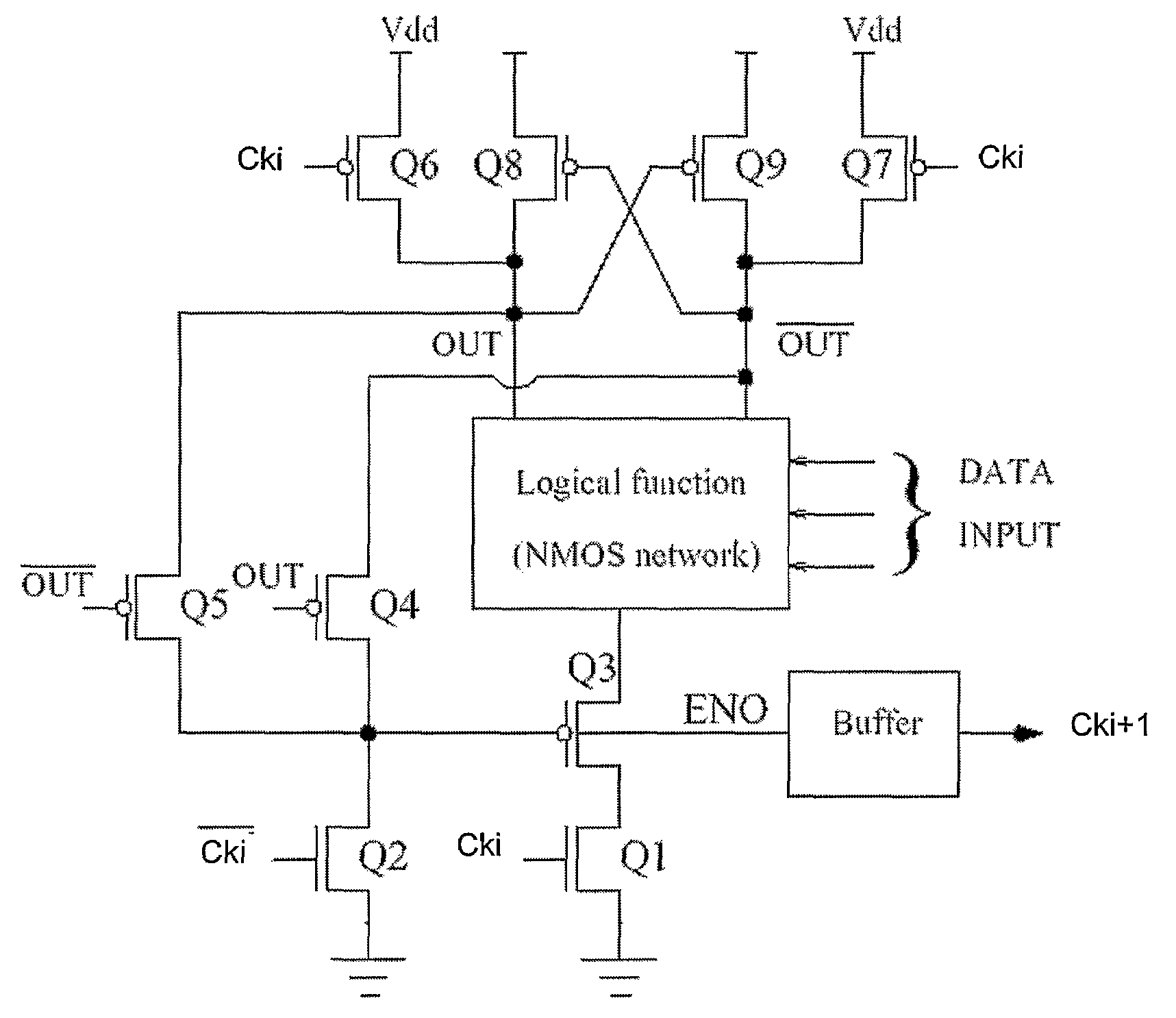
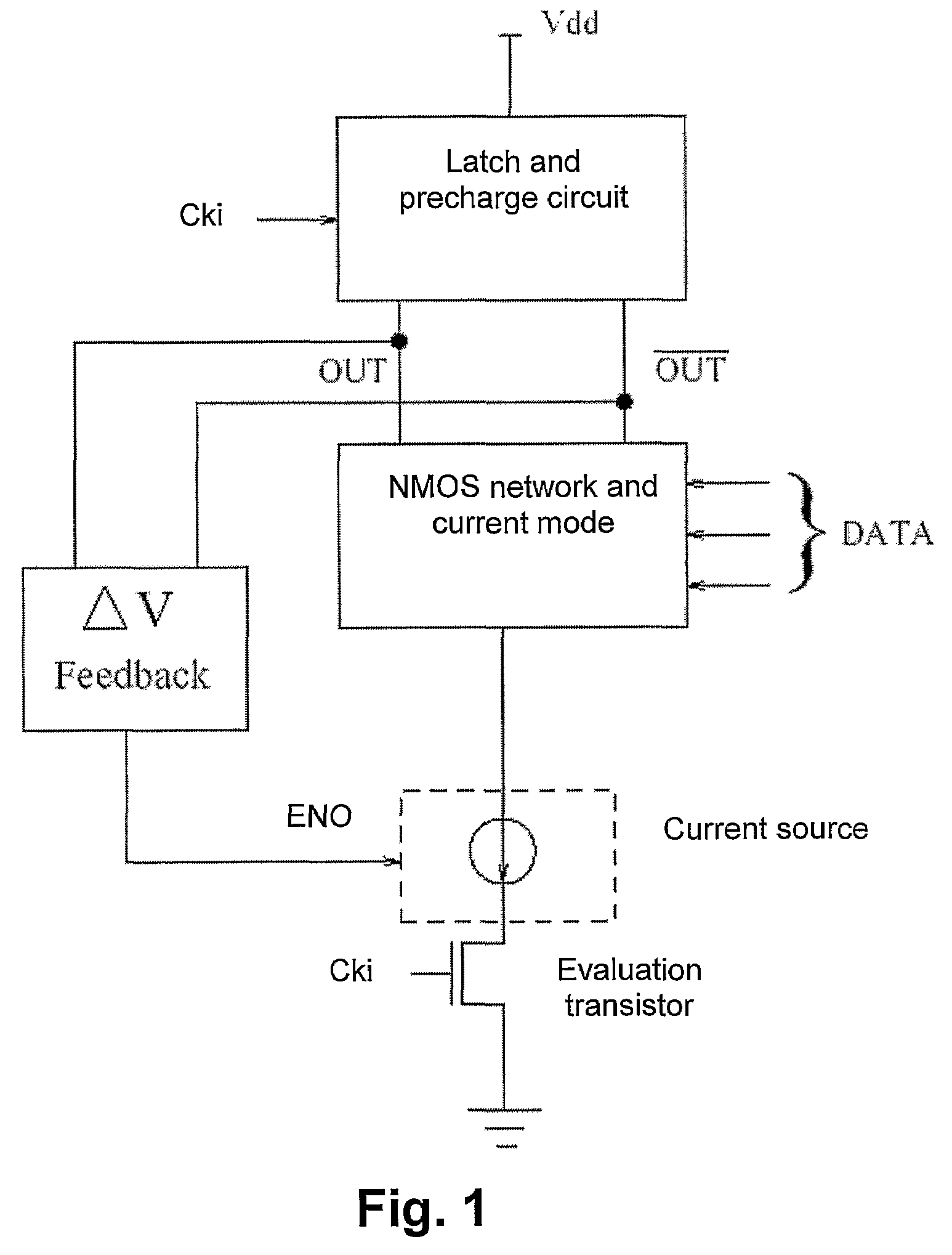
The present invention provides a low swing current mode logic circuit including: a current mode logic block having data inputs and outputs; a pre-charging circuit for pre-charging the outputs; a dynamic current source; an evaluation circuit for evaluating the logic block during an evaluation phase; and, a feedback path arranged between the outputs and the dynamic current source which is responsive to a difference between the outputs. The simplicity of generating the low swing, achieved by the feedback which may be implemented by only two transistors, is in contrast with the complexity introduced by some methods used by other logic styles for achieving low swing.

Description

[0001]This application is a 371 of PCT / BE05 / 00077 filed on May 13, 2005; which claims benefit of U.S. Provisional Application No. 60 / 571,383, filed May 14, 2004, is claimed and the entire content thereof is incorporated herein by reference.TECHNICAL FIELD OF THE INVENTION[0002]The present invention relates to a logic circuit featuring low power consumption, as well as to applications including such logic circuit.BACKGROUND OF THE INVENTION[0003]Integrated circuits form an essential part of modern electronic equipment. There is an increasing reliance on portable equipment with intensive processing requirements and limited battery life. In view of this, there is considerable interest in a logic style, which offers low power consumption.[0004]Some logic styles are based on decreasing the swing of the signal (reduced swing technique) so as to reduce power consumption.[0005]One of such logic styles is the Short Circuit Current Logic (SCL) as described by Fahim A. M. et Elmasry M. I. in “...

Claims


Application Information

Patent Timeline
Patent Type & Authority Patents(United States)
IPC IPC(8): H03K19/094H03K19/017H03K19/096H03K19/173
CPCH03K19/09432H03K19/0963H03K19/1738
Inventor HASSOUNE, ILHAMLEGAT, JEAN-DIDIER
Owner UNIVERSITE CATHOLIQUE DE LOUVAIN
Why Eureka
Try Eureka