Method for combustion of a fuel

a fuel and combustion method technology, applied in the field of fuel combustion methods, can solve the problems of reducing reducing the efficiency of combustion, and reducing so as to minimize the residence time and the risk of pressure pulses, and the effect of widening the operating or load rang

Inactive Publication Date: 2008-04-29
ANSALDO ENERGIA SWITZERLAND AG
View PDF22 Cites 85 Cited by
  • Summary
  • Abstract
  • Description
  • Claims
  • Application Information

AI Technical Summary

Benefits of technology

[0012]If the present method is used in the burner system of a gas turbine installation, the inlet temperature of a premixed combustible fluid mixture is typically between 400 and 500° C., i.e. below the spontaneous ignition threshold value for a lean mix with, for example, λ=2. The use of the abovementioned burner system and of the feed of the reactants involved in an open jet with a sufficiently high velocity produces a strong jet-induced recirculation of the flue gas in the combustion space, with part of the flue gas being entrained with the emerging jets, and the reaction mixture being highly diluted as a result. At the same time, jet-induced recirculation internally within the combustion space increases the temperature of the reaction mixture to above the spontaneous ignition threshold value, so that the reaction mixture ignites spontaneously, and on account of the strong dilution combustion takes place with an invisible volumetric flame. This leads to very robust and reliable combustion with a uniform temperature profile and the potential for greatly reduced pollutant emissions. Furthermore, this combustion technique has the potential to interrupt the Rayleigh mechanism, so that pressure pulses, as occur with the lean combustion which has hitherto been used in gas turbine installations, are suppressed. By suitable selection or alteration of injection parameters, the present method allows a gas turbine installation to operate stably over a wide load range. Tests have shown that in gas turbine installations, at the high-pressure conditions prevailing therein-together with low-fuel conditions, for example λ=2, even a flue gas recirculation rate in the region of 100% is sufficient to generate the flameless combustion mode. The recirculation rate KV is in this context defined as the ratio between the mass flow of the recirculated flue gas and the mass flow of the fresh combustible fluid fed to the combustion chamber:
[0020]High flue gas recirculation rates cause a not inconsiderable increase in the levels of H2O in the combustion system; Similarly to the injection of water or steam into a combustion system, this increase has an additional positive influence on suppressing the formation of NOx, since the result is the formation of a heat sink, keeping the process temperature controllable. Furthermore, the dissociation of H2O in the hot reaction zone is likely to lead to a higher level of OH radicals, which therefore increases the destruction of N2O.
[0045]With the present method and the associated burner, it is possible, in part in combination with the particular embodiments, to completely exhaust the chemical kinetic potential of the flameless combustion for a gas turbine installation. This relates in particular to achieving high recirculation rates at low pressure losses, a high degree of mixing upstream of the combustion, reliable combustion, a high flame stability, low emissions and low combustion oscillations. The method according to the invention can be realized very successfully in a gas turbine installation with a recirculation rate KV of 100%<KV<200%. It is preferable for the method to be operated with a recirculation rate of 100%<KV<150%. It is preferable for the majority, and very particularly preferably all, of the flue gas to be admixed to the combustible fluid open jet by the jet-induced recirculation internally within the combustion space which has been described above. This means that there is no need for complex structural means for external recirculation of flue gas in an apparatus for carrying out the method.
[0048]The choice of geometric arrangement and configuration of the individual entry nozzles of the present burner system and of the mode of operation in accordance with the variant embodiments explained above or presented in the exemplary embodiments is in each case selected as a function of the geometry of the combustion chamber and the required residence time in the combustion chamber, in order to achieve complete combustion over the widest possible operating or load range. Significarit objectives in this context are to widen the flame volume and to minimize the residence time as well as the risk of pressure pulses.
[0049]In one operating mode of the method, the supply of fluid to the nozzles is pulsed. This likewise allows the mixing of combustible fluid and flue gas to be influenced. If a plurality of jets which are not pulsed in phase are used, improved mixing with a reduced risk of pressure pulses in combustion is achieved. This effect is likewise achieved with a cyclical, intermittent or oscillating supply of combustible fluid.
[0050]According to the invention, therefore, a method of the type described in the introduction, on account of the use of the jet-induced flue gas recirculation internally within the combustion space, can be operated without flue-gas recirculation apparatus of complex design, and allows extremely flexible adaptation to a wide operating range.

Problems solved by technology

Secondly, the lowest possible emissions of pollutants, i.e. in particular NOx and CO, need to be realized.
However, one drawback of the high air preheating temperatures is higher peak temperatures in the flame, which have a disastrous effect on the thermal formation of nitrogen oxides.
One problem with realizing a method of this type is the recirculation of a sufficient quantity of flue gas.
The recirculation is also difficult to implement because burner systems usually have a not inconsiderable pressure loss, so that the total pressure of the flue gas to be recirculated is below that of the fresh gas supplied.
Overall, the recirculation of sufficient quantities of flue gas using conventional recirculation techniques is only possible with considerable difficulty, if at all.

Method used


Image

  • Method for combustion of a fuel
  • Method for combustion of a fuel
  • Method for combustion of a fuel

Examples


Embodiment Construction

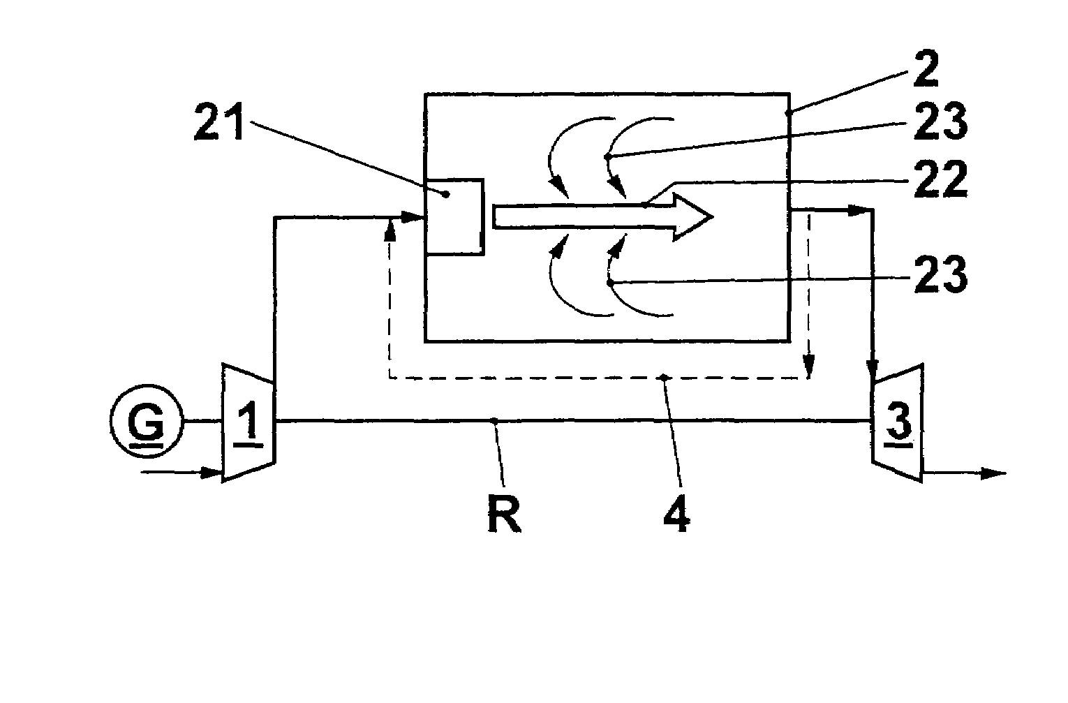
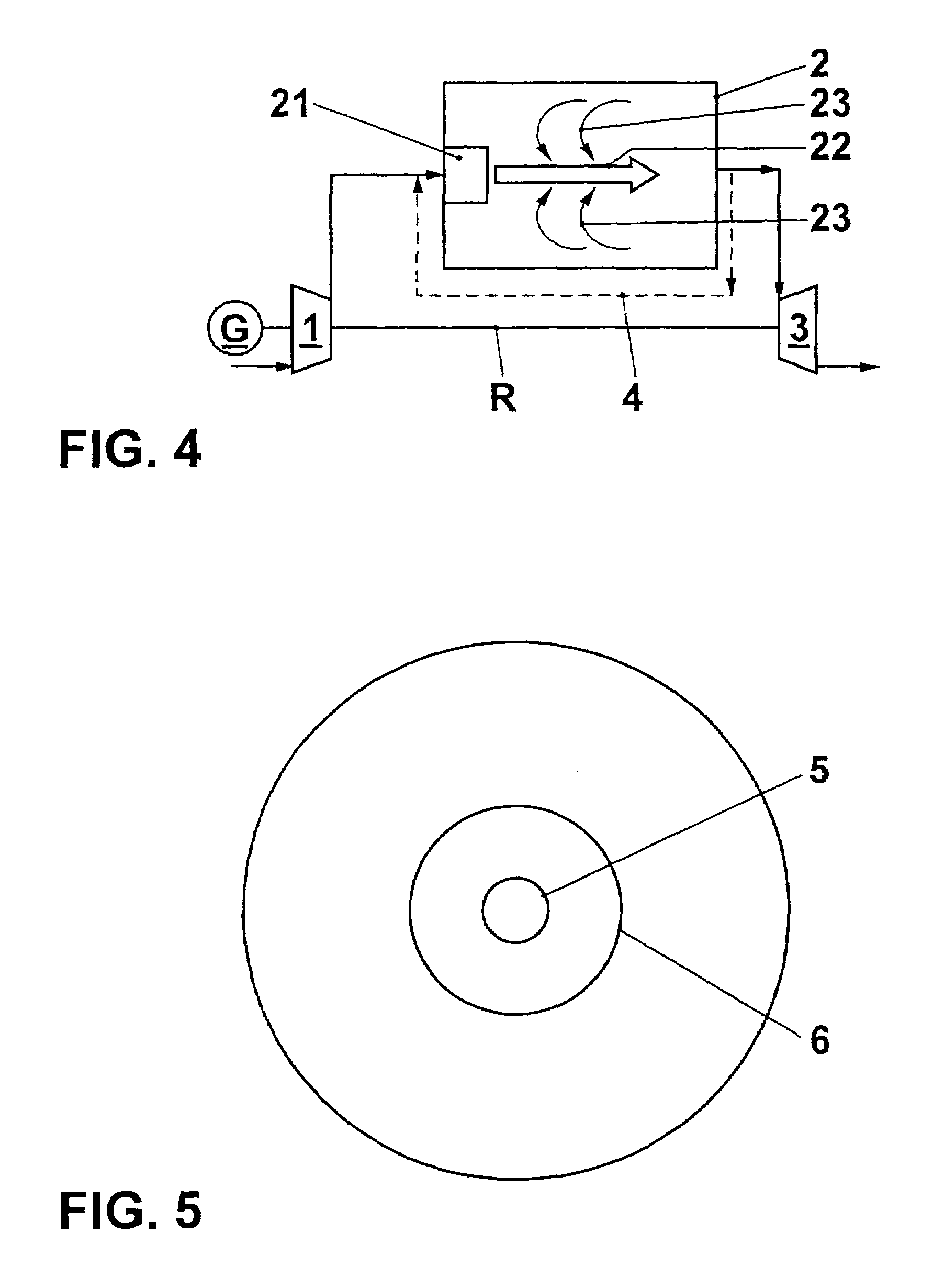
[0063]FIG. 4 diagrammatically depicts a gas turboset. A generator G, a compressor 1 and a turbine 3 are arranged on a common shaft R. The compressor 1 compresses ambient air and delivers it into a combustion chamber 2, where a fuel is burnt in the air. The hot and confined flue gases formed drive the turbine 3. The turbine 3 in turn drives the compressor 1 and the generator G. The combustion in the combustion chamber 2 is intended to take place as spontaneously igniting volumetric combustion of the type described above. The increase in the temperature of a fuel / air mixture provided in the burner 21 to the spontaneous ignition temperature is intended to be effected by admixing hot flue gas which has been recirculated from the combustion chamber. One possible way of doing this is external flue gas recirculation along the path marked by 4. As explained above, this cannot generally be realized without problems. According to the invention, therefore, the flue gas is admixed with the comb...


PUM


Abstract

In a method for the combustion of a fuel, a fuel or a premixed combustible mixture is introduced into a combustion space as a combustible fluid open jet. The velocity of the open jet is selected in such a way that it is impossible for a stable flame front to form, i.e. is in any event greater than the flame front velocity, and that, on account of a jet pump effect, flue gas is mixed into the combustible fluid jet from the combustion chamber in a jet-induced recirculation internally within the combustion chamber. The admixed flue gas dilutes and heats the combustible fluid. The heating causes the spontaneous ignition temperature to be exceeded, and a low-pollutant volumetric flame is formed in a highly dilute atmosphere.

Description

CROSS-REFERENCE TO RELATED APPLICATIONS[0001]This application is a continuation of the U.S. National Stage designation of co-pending International Patent Application PCT / EP03 / 50916 filed Dec. 1, 2003, which claims priority to German patent application no. 102 57 704.8 filed Dec. 11, 2002, and the entire contents of these applications are expressly incorporated herein by reference thereto.FIELD OF THE INVENTION[0002]The present invention relates to a method for the combustion of a fuel, in particular in the combustion chamber of a gas turboset. It also relates to an apparatus for carrying out the method.BACKGROUND OF THE INVENTION[0003]Two inherently contradictory objectives are being pursued when generating energy through combustion of fossil fuels. Firstly, the efficiency which can be achieved is supposed to be lowered in order to save on fuel energy and to reduce the emissions of CO2. Secondly, the lowest possible emissions of pollutants, i.e. in particular NOx and CO, need to be ...

Claims


Application Information

Patent Timeline
Patent Type & Authority Patents(United States)
IPC IPC(8): F02C7/08F02G1/00F02G3/00F23C9/00F23R3/28F23R3/34
CPCF23C9/006F23R3/286F23R3/343F23C2900/09002F23C2900/99001F23R2900/03282Y02E20/342Y02E20/34
Inventor CARREA, ELISABETTAJANSOHN, PETER
Owner ANSALDO ENERGIA SWITZERLAND AG
Why Eureka
Try Eureka