Tire parameter monitoring system with inductive power source

a technology of inductive power source and sensor system, which is applied in vehicle tyre testing, instruments, roads, etc., can solve the problems of limited battery life, relatively insensitive sensors to mechanical vibration, and limited useful lifetime of sensor system, etc., and achieves simple and inexpensive implementation.

Inactive Publication Date: 2008-04-29
SILICON VALLEY MICRO C CORPORATION
View PDF5 Cites 31 Cited by
  • Summary
  • Abstract
  • Description
  • Claims
  • Application Information

AI Technical Summary

Benefits of technology

[0010]The invention comprises a method and system for monitoring vehicle tire parameters which eliminates the need for a battery power source, and which is relatively simple and inexpensive to implement.
[0012]The power coil is preferably located on the substrate in a position surrounding the power system, the tire parameter sensor and the processor / transmitter unit in order to maximize the coil area and the potential number of coil turns.
[0018]The invention provides a convenient solution to the problem of providing an inexhaustible power source for supplying electrical power to tire parameter monitoring systems in wheeled vehicles. The system can be installed on a vehicle either during manufacture of a new vehicle or as an aftermarket item. Further, existing vehicles without tire parameter monitoring systems can easily be retrofitted with a state-of-the-art system at relatively low cost. This is particularly beneficial in jurisdictions which mandate certain tire parameter monitoring devices on all road vehicles. The sensor assembly is substantially lighter in weight than known assemblies requiring a battery to power the electronics. In addition, the useful lifetime of a sensor assembly fabricated according to the invention is only limited by the operational lifetime of the electronic components and the useful lifetime of the tire, which are substantially longer than the lifetime of a battery. Two or more sensor assemblies can be installed on the same tire to measure different tire parameters, such as internal tire pressure, tire wall temperature, internal air temperature, and the like. Lastly, due to their light weight and low cost, the sensor assemblies can be incorporated into the tire during the tire fabrication process so that the sensor assemblies are replenished when a new tire is installed on a vehicle.

Problems solved by technology

This type of sensor is relatively insensitive to mechanical vibrations, which are regularly encountered in an automotive environment.
However, the useful lifetime of this sensor system is limited by the energy capacity of the battery used to electrically power the system.
More particularly, since the sensor circuitry is continuously powered by the essential battery when the vehicle electrical system is activated, the useful lifetime of the battery is limited by the battery energy capacity and the total activation time.
This drawback is compounded by the need for components having relatively small physical size due to installation constraints.
As a consequence, the size of the battery is severely limited, and battery replacement is a major constraint to the installed efficacy of such known sensor systems.
While the power saving unit described above does provide a substantial improvement in the useful lifetime of the system battery, and thus the overall system, all batteries have a finite energy capacity and eventually will be depleted.
If the battery cannot be replaced due to the design of the system, a new system must be installed.
Battery powered tire parameter monitoring systems also suffer from further disadvantages.
First, the cost of the battery relative to the other system components is relatively high.
The cost of a high quality lithium battery, for example, is approximately one-half the cost of the entire sensor assembly.
In addition, the battery adds appreciable weight to the system: essentially fifty percent of the system weight is due to the battery.
While effective in eliminating the battery, this design requires that each wheel be provided with the special hub assembly, which adds substantial expense to the sensor system and requires substantial technical expertise to install on the vehicle.
First, each antenna must be positioned closely adjacent the corresponding tag due to the relatively short effective energy transfer range inherent in an RFID tag system.
Efforts to provide a battery-less tire parameter sensor system devoid of the above-noted disadvantages have not been successful to date.

Method used


Image

  • Tire parameter monitoring system with inductive power source
  • Tire parameter monitoring system with inductive power source
  • Tire parameter monitoring system with inductive power source

Examples


Embodiment Construction

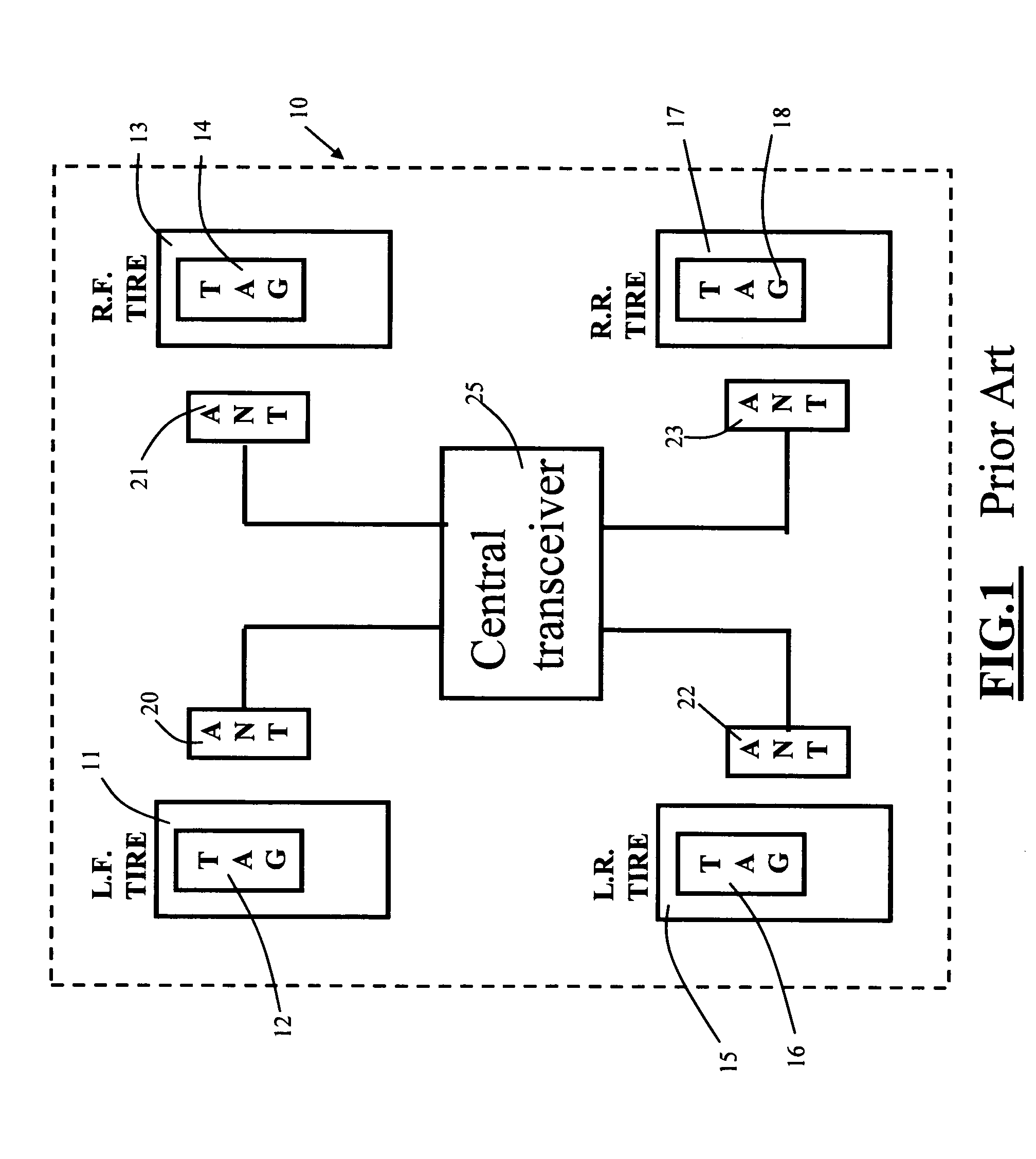
[0028]Turning now to the drawings, FIG. 1 is a schematic view of the above-described prior art tire parameter monitor system using RFID tags configured as passive transponders and electrical operating power derived from electromagnetic energy received from associated antennae when activated by the central transceiver 25. The limitations and disadvantages of the FIG. 1 system are set forth above.

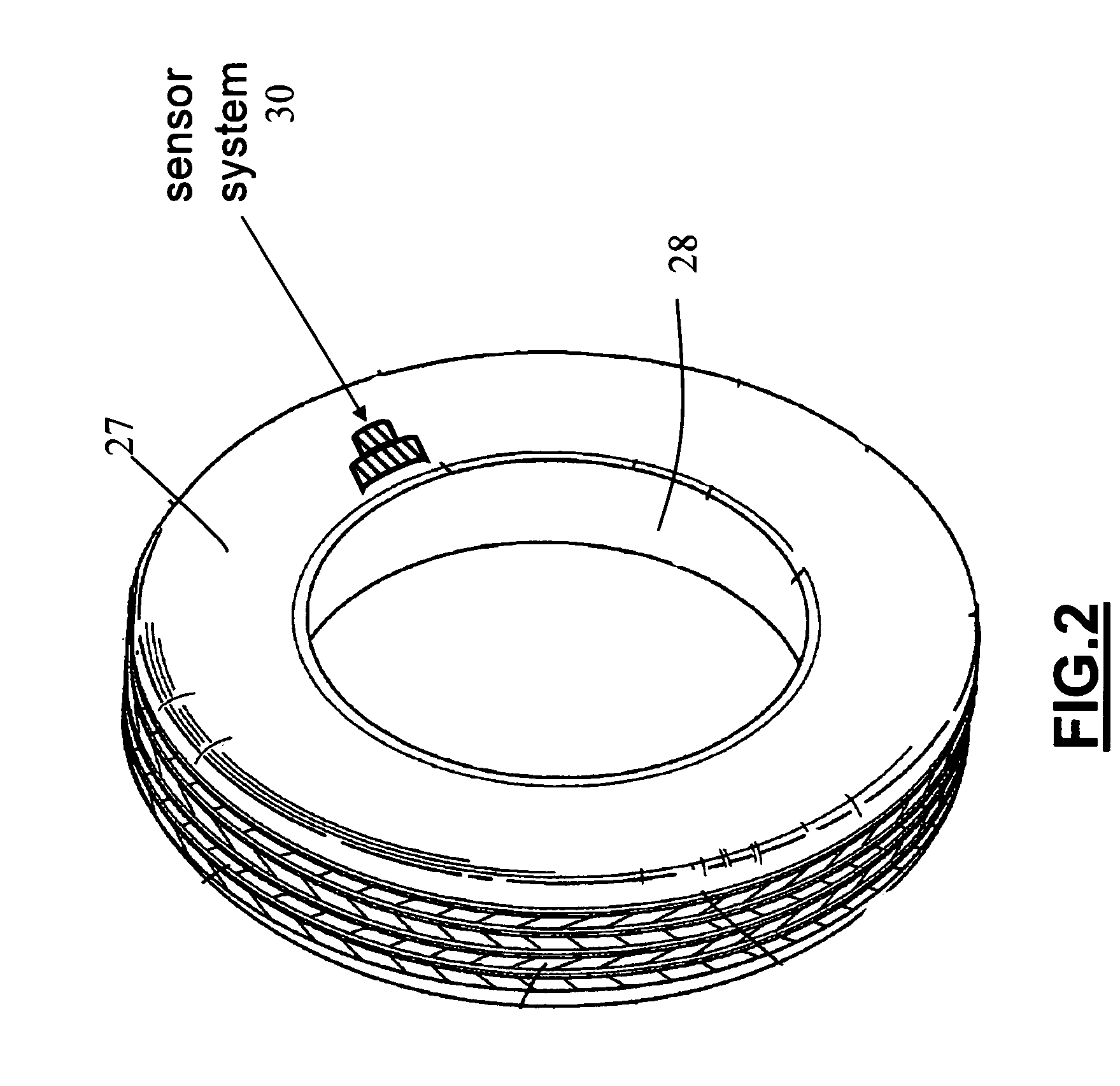
[0029]FIG. 2 is a perspective view of a single wheel and tire showing a tire parameter sensor mounted on the side wall surface of the tire. As seen in this FIG., a vehicle tire 27 is mounted on a wheel 28. Mounted on the side wall of tire 27 is a tire parameter sensor assembly 30 illustrated in detail in FIGS. 3-5.

[0030]FIG. 3 is a top plan view showing tire parameter sensor assembly 30 according to the invention. As seen in this FIG., sensor assembly 30 includes a tire parameter sensor 31, a combination microcomputer unit / transmitter 32 (MCU / transmitter 32), an antenna 33, a power system 34,...


PUM


Abstract

A battery-less tire parameter sensor system for monitoring a vehicle tire parameter such as pressure and temperature. A sensor assembly has a power system, a processor / transmitter, a sensor, and a power coil mounted on a substrate. This assembly is mounted on or in the side wall or tread wall of a tire. A magnet is mounted on the vehicle in proximity to the path of the power coil during tire rotation. The moving power coil passes through the magnetic field and generates operating voltage for the sensor assembly components. The power system includes a voltage multiplier, a voltage regulator, and a storage capacitor. Two or more sensor assemblies can be mounted on the same tire to monitor different parameters.

Description

BACKGROUND OF THE INVENTION[0001]This invention relates to automotive tire parameter monitoring systems. More particularly, this invention relates to a tire parameter monitoring system powered by inductively generated D.C. electrical power.[0002]Tire parameter monitoring systems are known and are commonly used to monitor one or more parameters of interest in individual pneumatic tires of a vehicle and to provide an advisory signal to the driver, or an on-board computer system, whenever the monitored parameter in one or more of the vehicle tires reaches a value lying outside of a predetermined safe range. The parameter is typically internal tire pressure, tire temperature, internal tire air temperature, lateral tire force, or some other parameter of interest. The advisory signal is typically generated by an r.f. signal generator controlled by a microprocessor connected to the tire parameter sensor, the advisory signal being generated whenever the tire parameter measured by the sensor...

Claims


Application Information

Patent Timeline
Patent Type & Authority Patents(United States)
IPC IPC(8): G01M17/02
CPCB60C23/0433B60C23/0413B60C23/04B60C23/00
Inventor HUANG, SU SHIONGZHU, SHENGBO
Owner SILICON VALLEY MICRO C CORPORATION
Why Eureka
Try Eureka