
Apparatus and method for route summarization and distribution in a massively parallel router

a massively parallel router and approximation method technology, applied in frequency-division multiplex, data switching network, instruments, etc., can solve the problems of inability to handle line rate forwarding for high bandwidth links such as 10 gbps interfaces, inability to successfully route packets, and inability to handle line rate forwarding for high bandwidth links, etc., to reduce the requirements for forwarding table space and limit the bandwidth needed for internal route distribution

Inactive Publication Date: 2008-05-06
SAMSUNG ELECTRONICS CO LTD
View PDF3 Cites 56 Cited by
  • Summary
  • Abstract
  • Description
  • Claims
  • Application Information

AI Technical Summary

Benefits of technology

This approach reduces bandwidth requirements for internal route distribution, optimizes forwarding table space, and minimizes packet drops by routing packets to external routers with more visibility, enhancing high-speed performance and scalability.

Problems solved by technology

More recently, however, the packet transmission capabilities of high-bandwidth network paths and the increases in Internet traffic have combined to outpace the processing capacities of conventional routers.
Thus, conventional routers retain route information in a central location and do not distribute route information within the router.
The main disadvantage of prior art routers is the inability to handle line rate forwarding for high bandwidth links, such as 10 Gbps interfaces.
Also, when the table space limitations of current routers are exceeded, the routers drop routes from their routing tables or cease to learn new routes.
Thus, conventional routers drop packets that would be routable if adequate table space were available.
But there is only one default route for the whole router, so the chances of successfully routing the packet are small.

Method used


Image

  • Apparatus and method for route summarization and distribution in a massively parallel router
  • Apparatus and method for route summarization and distribution in a massively parallel router
  • Apparatus and method for route summarization and distribution in a massively parallel router

Examples


Embodiment Construction

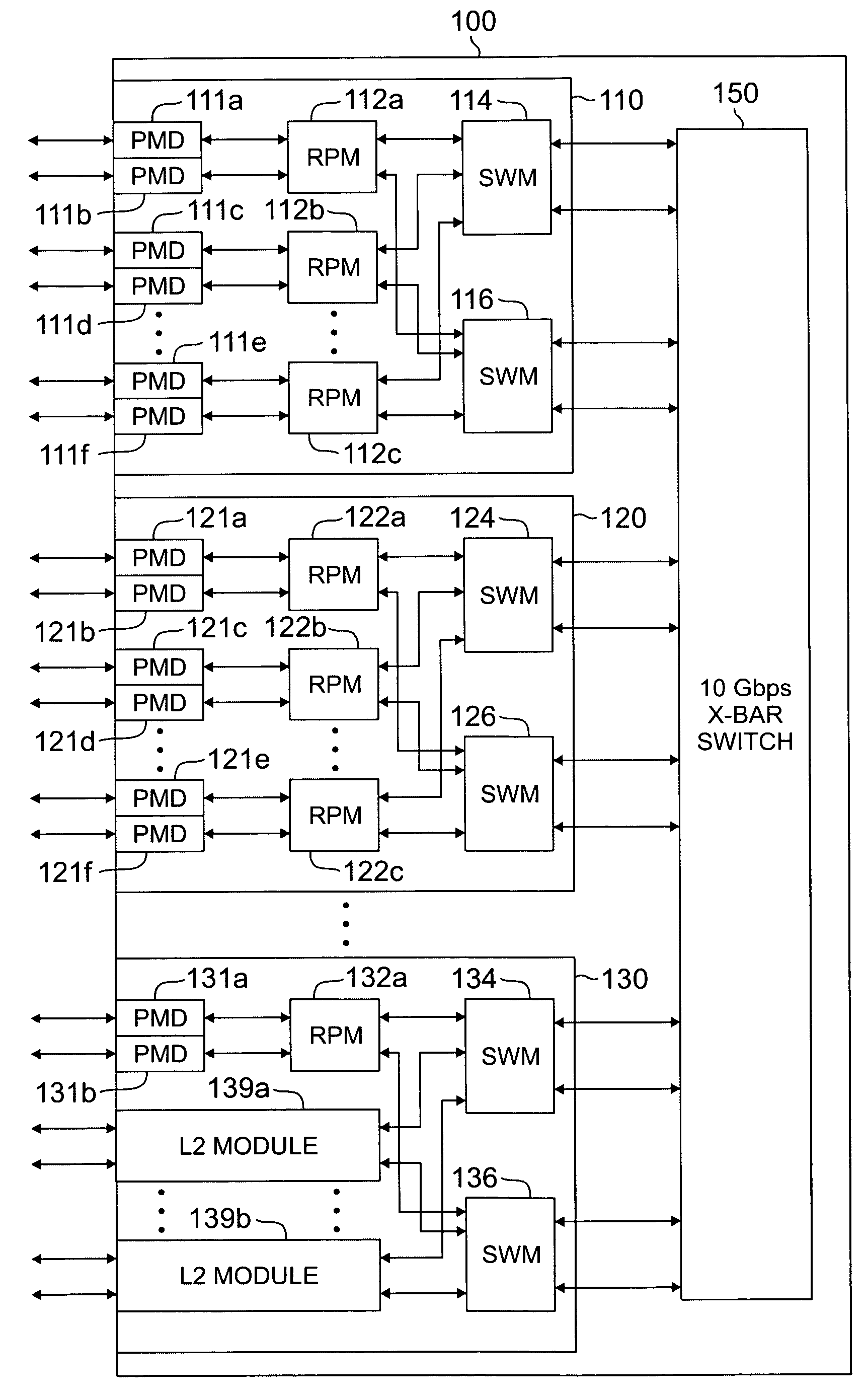
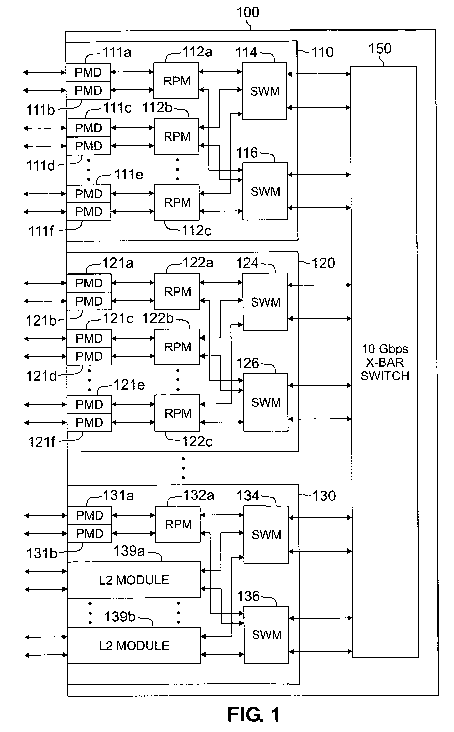
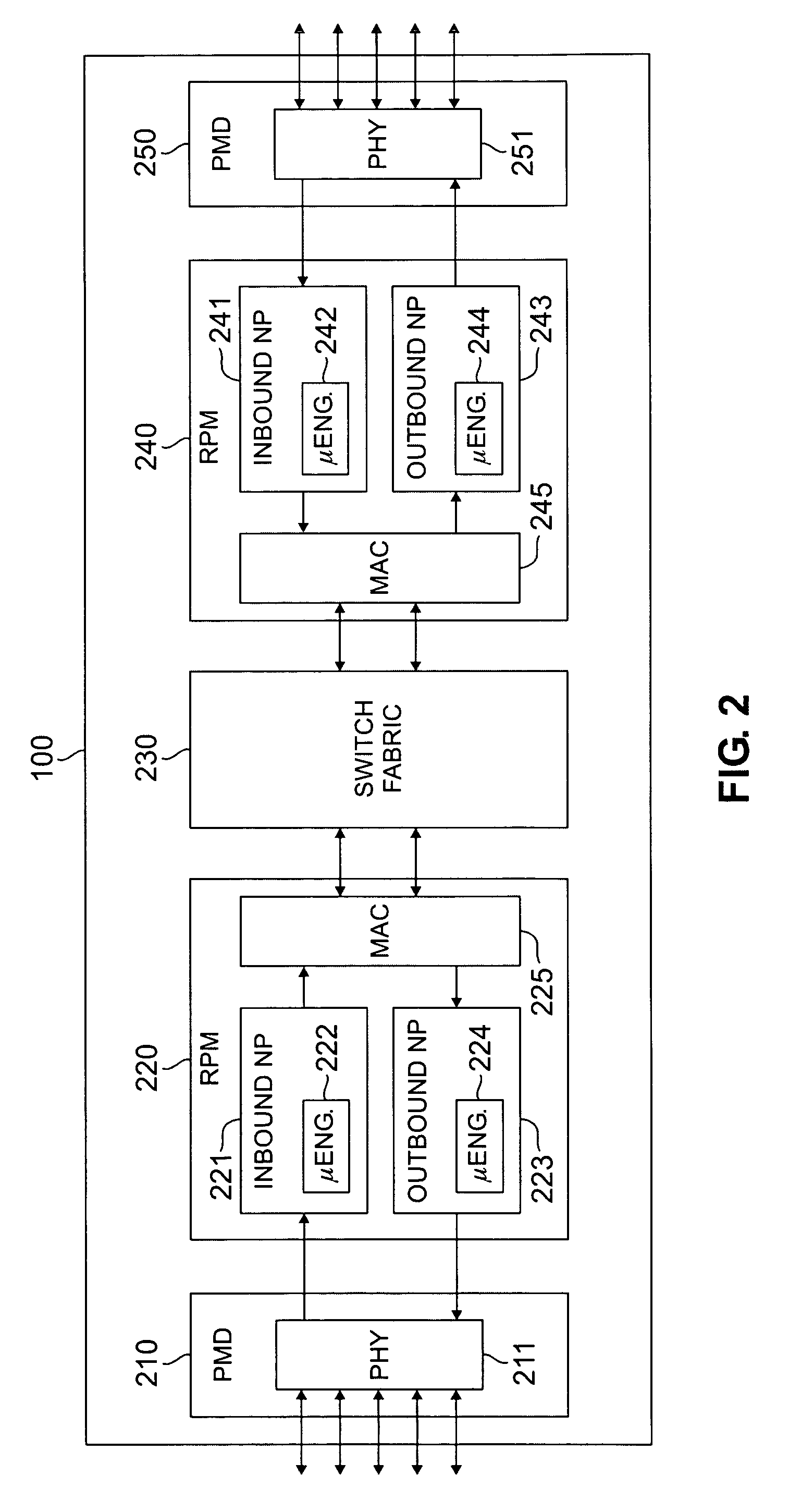
[0025]FIGS. 1 through 5, discussed below, and the various embodiments used to describe the principles of the present invention in this patent document are by way of illustration only and should not be construed in any way to limit the scope of the invention. Those skilled in the art will understand that the principles of the present invention may be implemented in any suitably arranged packet switch or router.

[0026]FIG. 1 illustrates exemplary distributed architecture router 100, which summarizes and distributes route information across plurality of routing nodes according to the principles of the present invention. Router 100 supports Layer 2 switching and Layer 3 switching and routing. Thus, router 100 functions as both a switch and a router. However, for simplicity, router 100 is referred to herein simply as a router. The switch operations are implied.

[0027]According to the exemplary embodiment, router 100 comprises N rack-mounted shelves, including exemplary shelves 110, 120 and...


PUM


Abstract

A router for interconnecting external devices coupled to the router. The router comprises a switch fabric and a plurality of routing nodes coupled to the switch fabric. Each routing node is capable of transmitting data packets to, and receiving data packets from, the external devices and is further capable of transmitting data packets to, and receiving data packets from, other routing nodes via the switch fabric. The router also comprises a control processor for comparing the N most significant bits of a first subnet address associated with a first external port of a first routing node with the N most significant bits of a second subnet address associated with a second external port of the first routing node. The router determines a P-bit prefix of similar leading bits in the first and second subnet addresses and transmits the P-bit prefix to other routing nodes.

Description

CROSS-REFERENCE TO RELATED APPLICATIONS AND CLAIM OF PRIORITY[0001]The present invention is related to that disclosed in U.S. Provisional Patent Application Ser. No. 60 / 488,197, filed on Jul. 17, 2003, entitled “Route Summarization and Distribution in a Massively Parallel Router.” Provisional Patent Application Ser. No. 60 / 488,197 is assigned to the assignee of the present application. The subject matter disclosed in Provisional Patent Application Ser. No. 60 / 488,197 is hereby incorporated by reference into the present disclosure as if fully set forth herein. The present invention claims priority under 35 U.S.C. §119(e) to U.S. Provisional Patent Application Ser. No. 60 / 488,197.TECHNICAL FIELD OF THE INVENTION[0002]The present invention is generally directed to distributed architecture routers and, in particular, to a massively parallel router that distributes summarized route prefix information to multiple routing nodes.BACKGROUND OF THE INVENTION[0003]There has been explosive grow...

Claims


Application Information

Patent Timeline
Patent Type & Authority Patents(United States)
IPC IPC(8): H04L12/28G06F15/173H04L12/56H04L12/26
CPCH04L45/00H04L45/583H04L45/7457H04L45/74591H04L45/645
Inventor WYBENGA, JACK C.STURM, PATRICIA K.FOSSATI, JORGE
Owner SAMSUNG ELECTRONICS CO LTD
Learn More