Regeneration of optical phase modulated signals

a phase modulation and optical technology, applied in the field of optical communication, can solve the problems of large amount of detection amplitude noise, errors, and limitation of dpsk transmission system accumulation of linear and nonlinear phase noise, and achieve the effect of simultaneously minimizing amplitude and phase nois

Inactive Publication Date: 2008-05-06
UNIV OF CENT FLORIDA RES FOUND INC
View PDF2 Cites 29 Cited by
  • Summary
  • Abstract
  • Description
  • Claims
  • Application Information

AI Technical Summary

Benefits of technology

[0019]A fourth objective of the present invention is to provide systems, apparatus, devices and methods for cascaded phase and amplitude regeneration, which combines the ideal phase regeneration results of an un-depleted pump PSA with a phase preserving limiting amplifier providing amplitude regeneration in separate nonlinear devices (or cascaded in the same device). The phase-regenerated signal serves as the input to the limiting amplifier, resulting in simultaneously minimized amplitude and phase noise at the output.

Problems solved by technology

DPSK systems with balanced detection can tolerate a large amount of amplitude noise compared to on-off keying since, in DPSK systems, errors occur only when pulse-to-pulse phase relationships deviate by more than π / 2 from their original values, regardless of the amplitude at detection.
Excluding timing jitter, the primary limitation of a DPSK transmission system is the accumulation of linear and nonlinear phase noise.
Linear phase noise results from imperfections in optical modulators and from amplified spontaneous emission in optical amplifiers.
As a result, amplitude noise from modulators, ASE, dispersion-induced pattern effects and nonlinearities such as inter-channel FWM all introduce nonlinear phase noise that limits system performance.
However these management schemes do not remove phase noise once it accumulates.
1619-1621, (2002), but does not correct for linear phase noise or the effects of inter-channel cross phase modulation.
However, these techniques have not been demonstrated experimentally.

Method used


Image

  • Regeneration of optical phase modulated signals
  • Regeneration of optical phase modulated signals
  • Regeneration of optical phase modulated signals

Examples


Embodiment Construction

[0032]Before explaining the disclosed embodiments of the present invention in detail it is to be understood that the invention is not limited in its applications to the details of the particular arrangements shown since the invention is capable of other embodiments. Also, the terminology used herein is for the purpose of description and not of limitation.

[0033]The following is a list of the reference numbers used in the drawings an the detailed specification to identify components:

[0034]

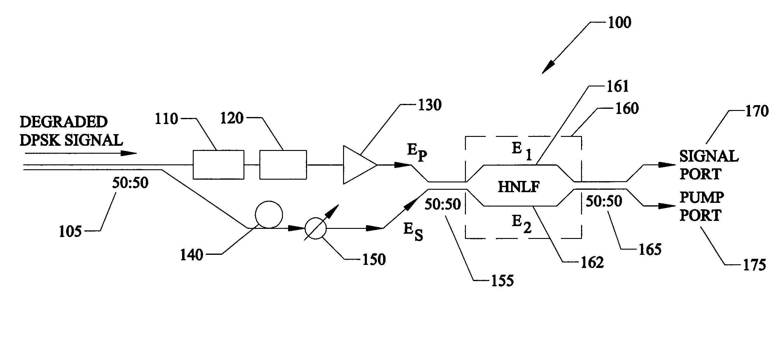
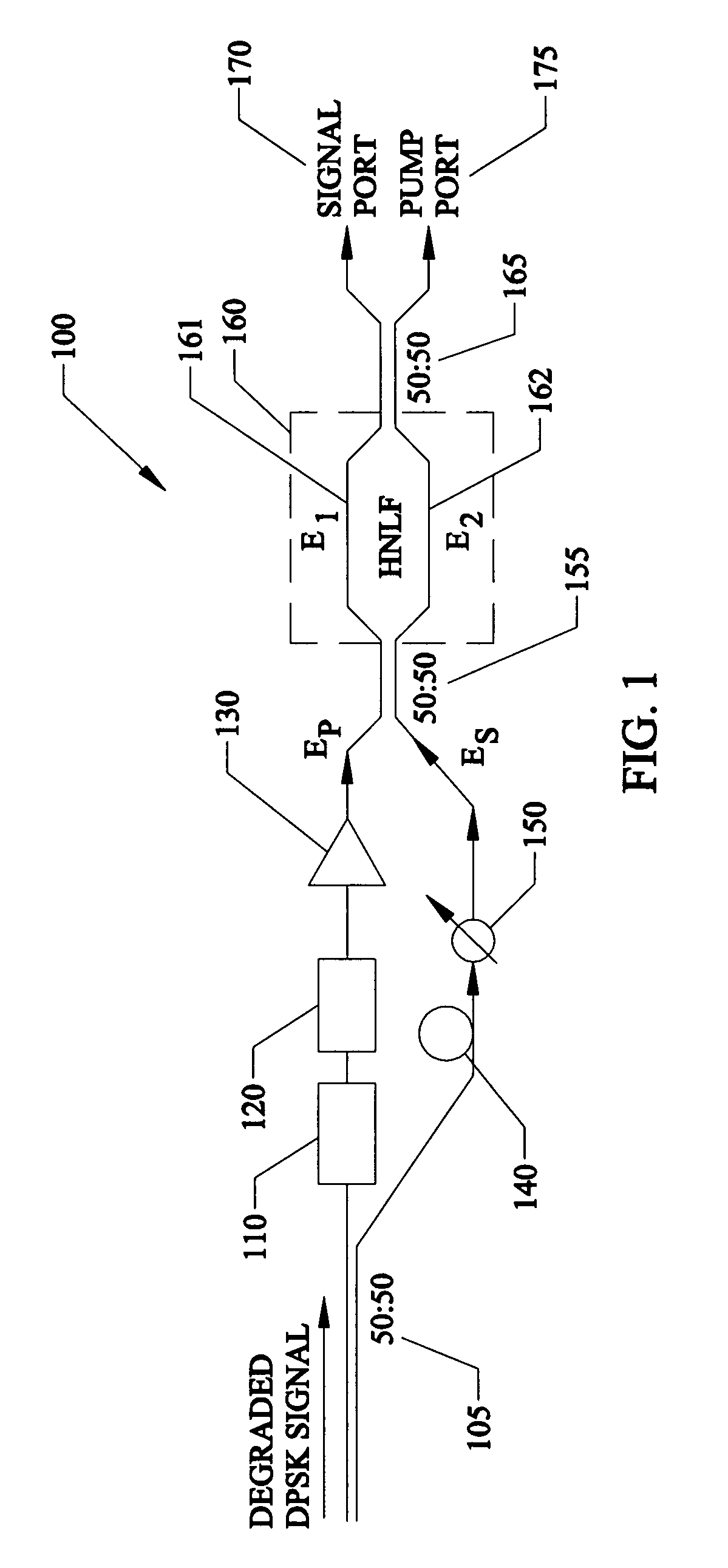
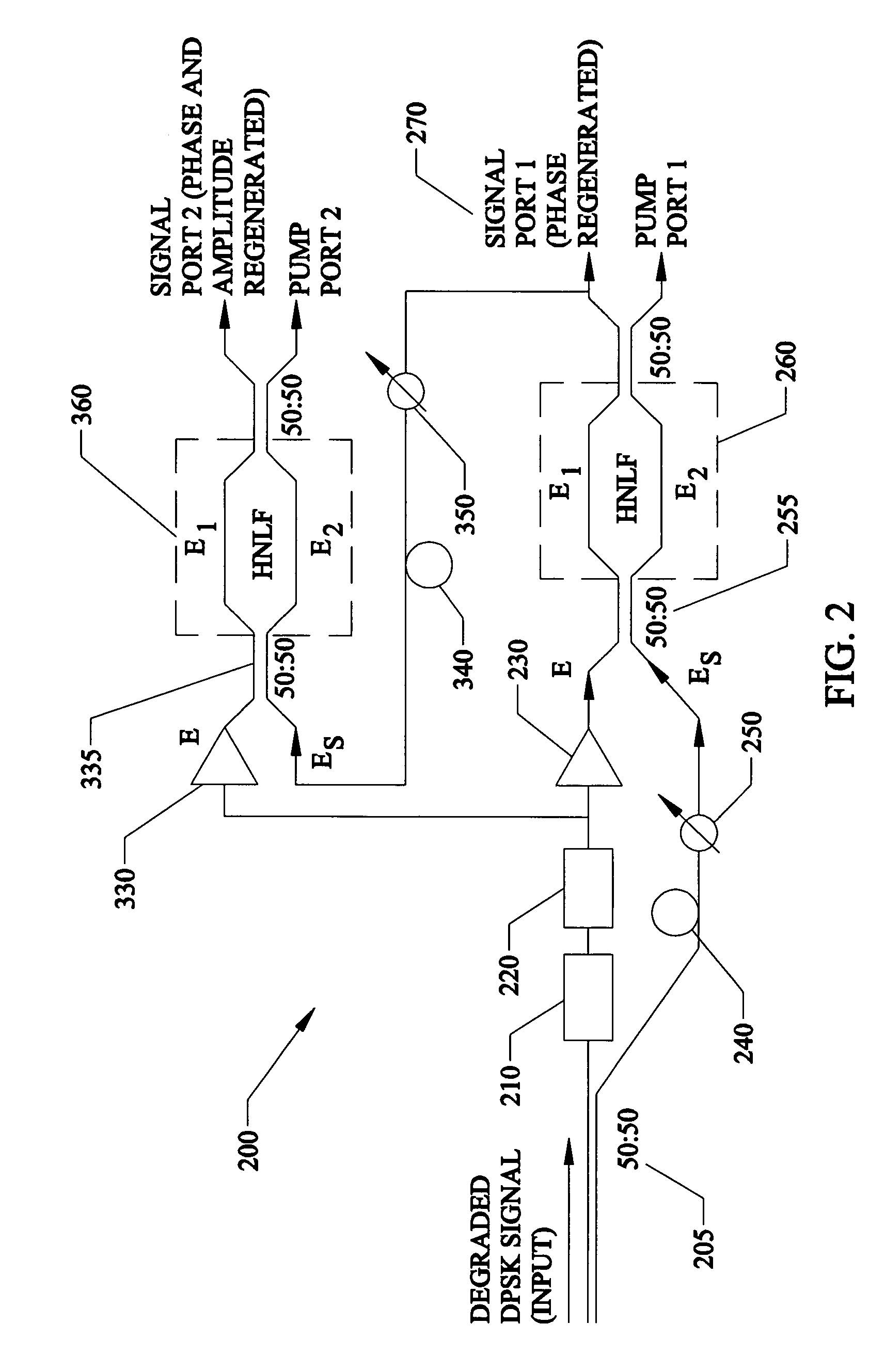
100phase-sensitive amplifier105first directional coupler110optical carrier recovery120local oscillator130optical amplifier140temporal delay150variable attenuator155second directional coupler160Mach-Zehnder interferometer161optical fiber E1162optical fiber E2165third directional coupler170signal port175pump port200cascaded phase-amplitude regenerator205first directional coupler210optical carrier recovery220local oscillator230first optical amplifier240temporal delay250variable attenuator255second direc...


PUM


Abstract

A regenerator for restoring the originally encoded optical phase of a differential-phase-shift-keyed signal. In an embodiment, the regenerator simultaneously provides limiting amplification and reduces amplitude noise based on a phase-sensitive optical amplifier that combines a weak signal field of a degraded input data with a strong pump field supplied by a local oscillator in a nonlinear interferometer. The two fields interact through degenerate four-wave mixing, and optical energy is transferred from the pump to the signal and vice versa. The phase sensitive nature of the optical gain leads to amplification of a specific phase component of the signal, determined by the input pump-signal phase difference and the incident signal phase is restored to two distinct states, separated by 180° according to the original encoding. Simultaneously, gain saturation of the pump wave by the signal wave results in limiting amplification of the signal wave for removing signal amplitude noise.

Description

FIELD OF THE INVENTION[0001]The present invention relates to the field of optical communications in general and in particular to systems, apparatus, devices, and methods for all-optical signal regeneration and optical processing of phase modulated signals in general and differential-phase-shift-keyed signals in particular.BACKGROUND OF THE INVENTION[0002]Differential phase-shift keying (DPSK) has become the format of choice for long-haul optical transmission systems, due to the 3-dB improvement in receiver sensitivity compared to on-off keying and enhanced tolerance to dispersion and nonlinear effects, particularly intrachannel four-wave mixing (FWM). DPSK systems with balanced detection can tolerate a large amount of amplitude noise compared to on-off keying since, in DPSK systems, errors occur only when pulse-to-pulse phase relationships deviate by more than π / 2 from their original values, regardless of the amplitude at detection. Excluding timing jitter, the primary limitation of...

Claims


Application Information

Patent Timeline
Patent Type & Authority Patents(United States)
IPC IPC(8): H04B10/02
CPCH04B10/299H01S3/06754H01S3/10007
Inventor CROUSSORE, KEVIN A.LI, GUIFANGKIM, CHEOLHWAN
Owner UNIV OF CENT FLORIDA RES FOUND INC
Why Eureka
Try Eureka