Supercharge Your Innovation With Domain-Expert AI Agents!

Traveling hydraulic working machine

a hydraulic working machine and traveling technology, applied in the direction of positive displacement liquid engine, fluid coupling, servomotor, etc., can solve the problems of reducing work efficiency in some type of work, affecting work efficiency, and affecting work efficiency, so as to improve both workability and work efficiency. , the effect of satisfying the combination of work

Inactive Publication Date: 2008-05-13
K C M
View PDF7 Cites 13 Cited by
  • Summary
  • Abstract
  • Description
  • Claims
  • Application Information

AI Technical Summary

Benefits of technology

"The present invention provides a traveling hydraulic working machine that can perform the maximum pump torque reducing control while accurately confirming a work situation during the combined operation of travel and a working actuator. The machine comprises first detecting means for detecting whether the sum of absorption torque of the hydraulic pump and travel torque exceeds the output torque of the prime mover, second detecting means for detecting the operating situation of the traveling means, and pump torque modifying means for modifying maximum absorption torque of the hydraulic pump depending on the operating situation of the traveling means. This allows for a satisfactory combination of work and improved workability and efficiency."

Problems solved by technology

Accordingly, a satisfactory result is obtained in limited types of work, whereas the workability deteriorates and the working efficiency decreases in some type of work.
Also, assuming the case that the front load is increased in a state where, for example, snow removing work is carried out at a constant speed while lowering a boom, if the maximum pump torque reducing control is performed, a larger travel force is produced and the snow removing work cannot be carried out at the constant speed.

Method used


Image

  • Traveling hydraulic working machine
  • Traveling hydraulic working machine
  • Traveling hydraulic working machine

Examples


first embodiment

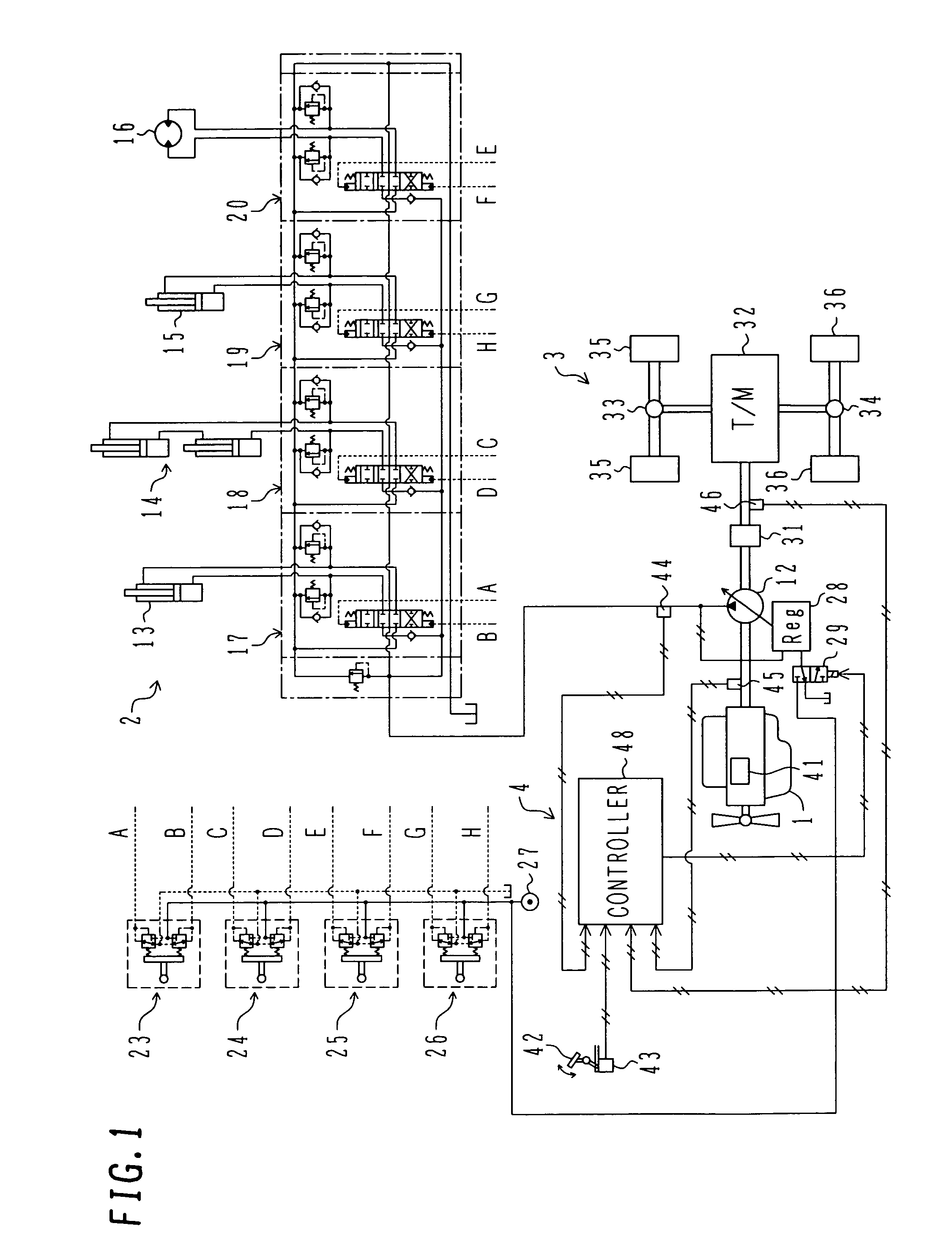
[0083]FIG. 1 is a diagram showing an overall system of a traveling hydraulic working machine according to the present invention.

[0084]In FIG. 1, the traveling hydraulic working machine according to this embodiment comprises a diesel engine (hereinafter referred to simply as an “engine”) 1 serving as a prime mover, a working system 2 and a traveling system 3 both driven by the engine 1, and a control system 4.

[0085]The engine 1 includes an electronic governor 41, and the electronic governor 41 adjusts a fuel injection amount depending on a control input applied from an accelerator pedal 42 (i.e., an accelerator control input), to thereby regulate the revolution speed of the engine 1. In other words, the accelerator pedal 42 serves as a means operated by an operator and commanding an engine revolution speed as a target (hereinafter referred to simply as a “target revolution speed”). The target revolution speed is set depending on the amount by which the accelerator pedal is pressed do...

second embodiment

[0136]the present invention will be described with reference to FIGS. 10 and 11. Note that, in FIGS. 10 and 11, components identical to those in FIGS. 1 and 4 are denoted by the same symbols.

[0137]In FIG. 10, a traveling hydraulic working machine according to this embodiment comprises an engine 1, a working system 2, a traveling system 3, and a control system 4A. The working system 2 and the traveling system 3 have the same constructions as those in the first embodiment shown in FIG. 1.

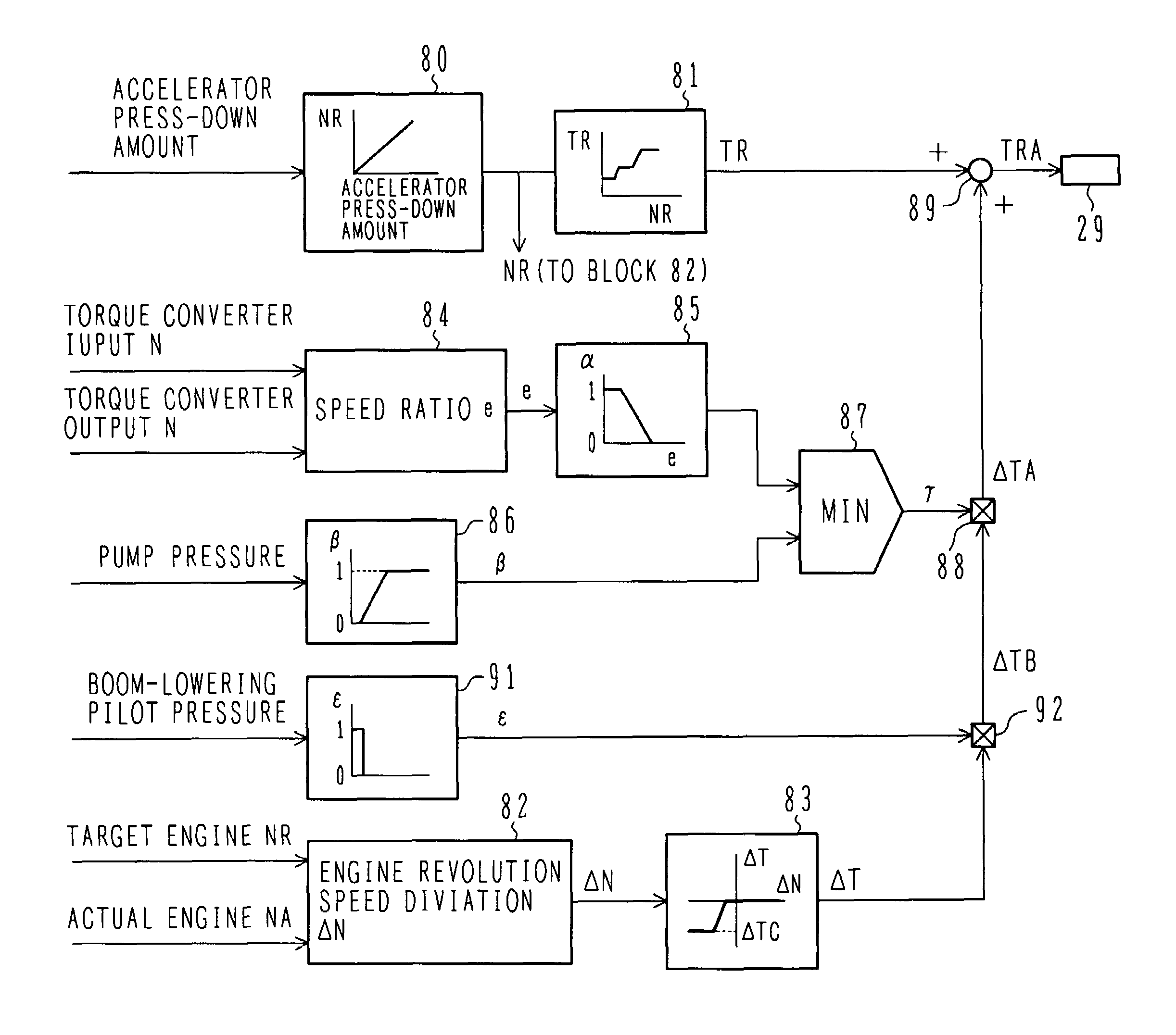
[0138]The control system 4A includes, in addition to the components in the first embodiment shown in FIG. 1, a pressure sensor 61 for detecting, as the operating situation of the working system 2, the pilot pressure in the direction in which the hydraulic actuator 13 is contracted (i.e., the boom-lowering pilot pressure) from among the pilot pressures outputted from the control lever units 23. A controller 48A executes predetermined arithmetic and logical operations based on signals from the position ...


PUM


Abstract

A modification torque ΔT and a torque converter speed ratio e is computed from input and output revolution speeds of a torque converter 31. A first determination coefficient α corresponding to the speed ratio e, and a second determination coefficient β corresponding to a pump pressure are computed. A selector 87 selects the smaller one of these coefficients as a determination coefficient γ, and the modification torque ΔT is multiplied by γ to provide a modification torque ΔTA. An adder 89 adds the modification torque ΔTA (negative value) to a pump base torque TR to provide a modified pump base torque TRA, whereby a maximum pump absorption torque TRA is controlled so as to become TRA. The maximum pump torque reducing control can then be performed while accurately confirming a work situation during the combined operation of travel and a working actuator.

Description

TECHNICAL FIELD[0001]The present invention relates to a traveling hydraulic working machine, such as a wheel loader or a telescopic handler, in which a transmission is driven by a prime mover (engine) to travel the machine and a hydraulic pump is also driven by the prime mover to operate a working actuator, thereby carrying out predetermined work.BACKGROUND ART[0002]In a known general traveling hydraulic working machine, a hydraulic pump is of the fixed displacement type, and the maximum absorption torque of the pump is also constant (fixed). Therefore, a proportion at which the engine output torque is distributed between respective operations of the hydraulic pump and travel (transmission) is constant and so is a maximum torque for the travel.[0003]In connection with such a known general traveling hydraulic working machine, Japanese Patent No. 2968558 proposes an improved one employing a variable displacement hydraulic pump in such a manner that the maximum absorption torque of the...

Claims


Application Information

Patent Timeline
Patent Type & Authority Patents(United States)
IPC IPC(8): F16D31/02E02F9/22F04B49/00F04B49/06F15B11/00
CPCB60W10/30B66F9/0655B66F9/20E02F9/2235E02F9/2296F04B49/065F04B2203/0603F16H2059/467
Inventor NAKAMURA, TSUYOSHINAKAMURA, KAZUNORIHIRATA, TOICHISUGIYAMA, GENROKUITOGA, KENTARO
Owner K C M
Features
  • R&D
  • Intellectual Property
  • Life Sciences
  • Materials
  • Tech Scout
  • Unparalleled Data Quality
  • Higher Quality Content
  • 60% Fewer Hallucinations
Learn More