On-board fuel fractionation system and methods to generate an engine starting fuel

a fuel fractionation system and engine technology, applied in the field of engine fuel systems to fuel powered engines, can solve the problems of further reduction of exhaust emissions, poor vaporization of a sufficient fraction of fuel, and undesirable air pollution from internal combustion engines, etc., to achieve faster separation, improve performance, usability and packaging

Inactive Publication Date: 2008-05-13
BOARD OF RGT THE UNIV OF TEXAS SYST
View PDF11 Cites 36 Cited by
  • Summary
  • Abstract
  • Description
  • Claims
  • Application Information

AI Technical Summary

Benefits of technology

[0012]In view of the foregoing, embodiments of the present invention beneficially provide a Fuel Fractionation System (FFS) and associated methods, which are an evolution of the On-Board Distillation System (OBDS), and which provides a less complicated and less expensive system that more efficiently separates fuel into it various components to produce a secondary fuel. Beneficially, the secondary fuel beneficially can have a composition by volume of between 80-100% hydrocarbons with a carbon number of six or below. Beneficially, the system can provide an improved air-fuel mixture at engine start-up, can provide for enhanced catalytic converter heating (and thus, higher efficiency), can reduce operating energy requirements, can reduce any inherent increase in evaporative emissions, and, as a result, can reduce total hydrocarbon emissions.
[0015]A vaporizing module is positioned adjacent the lower end portion of the housing to at least partially vaporize the feed fuel to enhance separation of the feed fuel into light fraction fuel and heavy fraction fuel components. A condensing module is positioned adjacent the upper end portion of the housing to condense heavy fraction fuel so that fuel exiting the light fraction output port is substantially light fraction fuel components by volume. A packed column including, for example, a three-dimensional column of porous metal is positioned within the housing between the vaporizing module and the condensing module to enhance fuel distillation. The enhanced surface area provided by the porous metal results in enhanced recirculation within the distillation column, improved concentration of the light end vapors at the top of the column, and improved concentration of heavy ends components at the bottom.
[0016]The controller provides control of the vaporization of the feed fuel by the vaporizing module and control of the condensation of the heavy ends or heavy fraction components by the condensing module responsive to various sensory inputs. The controller can ensure that the bottom of the distillation column is heated with a heating rate such that vapor generation occurs in the column at a desired temperature and pressure, and can ensure that the top of the distillation column is cooled such that condensation occurs at a desired temperature and pressure, resulting in the production of secondary fuel having the appropriate and desired characteristics.
[0017]The system can also include a heat exchanger to preheat the distillation column feed fuel stream and cool the hot heavy ends stream exiting the distillation column bottom. The heat exchanger beneficially can accomplish two major tasks. First, the heat exchanger can help mitigate concerns about increasing evaporative emissions due to increase in main fuel tank temperature by sending cooler fuel to the main fuel tank. Second, the heat exchanger can help conserve energy that would otherwise need to be applied in the distillation column by recovering heat that would ordinarily be sent to the main fuel tank or elsewhere.
[0018]According to another embodiment of the present invention, provided is a fuel fractionating system for an engine having a fuel intake. The system can include a main fuel tank for supplying a primary feed fuel to the engine, and a distillation column assembly to distill fuel to form a volatile light fraction secondary fuel from a portion of the primary feed fuel. The distillation column assembly can include a distillation column including a housing having an upper end portion, a lower end portion, and a medial portion extending therebetween, and a fuel feed port extending through the medial portion of the housing and positioned to receive feed fuel from the main fuel tank for distillation. A light fraction output port extends through the upper end portion of the housing and is positioned to allow output of distilled light fraction fuel. A heavy fraction output port extends through the lower end portion of the housing and is positioned to allow output of heavy fraction fuel. A vaporizing module is positioned adjacent the lower end portion of the housing to at least partially vaporize the feed fuel to separate the feed fuel into light fraction fuel and heavy fraction fuel components, and a condensing module is positioned adjacent the upper end portion of the housing to condense heavy fraction fuel components so that fuel exiting the light fraction output port is substantially light fraction fuel components by volume. The combination of the vaporizing module and condensing module synergistically results in the production of secondary fuel having the appropriate and desired characteristics.
[0020]Beneficially, embodiments of the present invention provide the FFS and associated methods are an evolution of the OBDS, and thus, contain significant improvements over the OBDS in terms of performance, usability and packaging, for example. Embodiments of an on-board FFS and methods to generate a starting fuel for gasoline-powered engines, for example, beneficially provide (1) compact packaging, (2) more efficient, faster separation, (3) no need to wait for the engine to reach fully warmed operating temperature, e.g., since a distillation column need not be heated by engine coolant as typically with OBDS, and (4) bottoms liquid from FFS that can be consumed directly by the engine. Embodiments of the present invention can also beneficially eliminate or reduce the concern of higher evaporative emissions from returning warm fuel to main fuel tank, and can also beneficially enhance engine power output through a combination of ignition timing advance and consumption of high-octane bottoms liquid. Beneficially, the FFS light fraction secondary fuel can be expected to feature at least five times the vaporization at moderate temperatures (21° C.-27° C.) than standard gasoline, resulting in decreased catalytic converter light-off times (at least 50%) and hydrocarbon emissions reductions on the order of 80-90% or more.

Problems solved by technology

Since as early as 1942, particularly in urban areas having a high concentration of motor vehicles, air pollution from internal combustion engines has been recognized as an undesirable consequence of a mobile society.
A major obstacle in achieving further reduction in exhaust emissions is the fact that in modern vehicles, 60-95% of hydrocarbon emissions occur during the first 30-90 seconds of operation of a vehicle engine following a cold start.
One of the primary factors is poor vaporization of a sufficient fraction of the fuel at start-up temperature (i.e., below 30° C.) to achieve stable combustion necessitates a generous over-fueling during the cranking and warm-up periods.
The over-fueling leads to high engine-out hydrocarbon emissions.
This problem is exacerbated as a result of significant over-fueling because the emission system catalyst (i.e., catalytic converter) does not achieve its optimum operating temperature until 1-2 minutes after a cold start, and thus, it is incapable of oxidizing all of the unburned fuel including that resulting from the generous over-fueling during start-up.
These systems were shown to be somewhat impractical, however, because the customer is required to fill two tanks, and the distribution network for dispensing gaseous fuels into vehicles is relatively sparse.
Both are actions that consumers generally find unacceptable.
Due to the difficulties and impracticalities of using two separate fuels and two fuel source systems, other systems were developed which separated a single fuel into two components, one being more volatile than the other one.
The systems, however, still had limitations, including the initial use of the primary fuel remaining in the fuel line at start-up, undesirable delays in starting the engine, the need for additional or complex pressurization and heating systems, efficient production of the volatile fuel, undesirable fuel tank heating resulting in increased evaporative emissions, and / or the use of complicated and expensive components.

Method used


Image

  • On-board fuel fractionation system and methods to generate an engine starting fuel
  • On-board fuel fractionation system and methods to generate an engine starting fuel
  • On-board fuel fractionation system and methods to generate an engine starting fuel

Examples


Embodiment Construction

[0033]The present invention will now be described more fully hereinafter with reference to the accompanying drawings, which illustrate embodiments of the invention. This invention may, however, be embodied in many different forms and should not be construed as limited to the illustrated embodiments set forth herein. Rather, these embodiments are provided so that this disclosure will be thorough and complete, and will fully convey the scope of the invention to those skilled in the art. Like numbers refer to like elements throughout. Prime notation, if used, indicates similar elements in alternative embodiments.

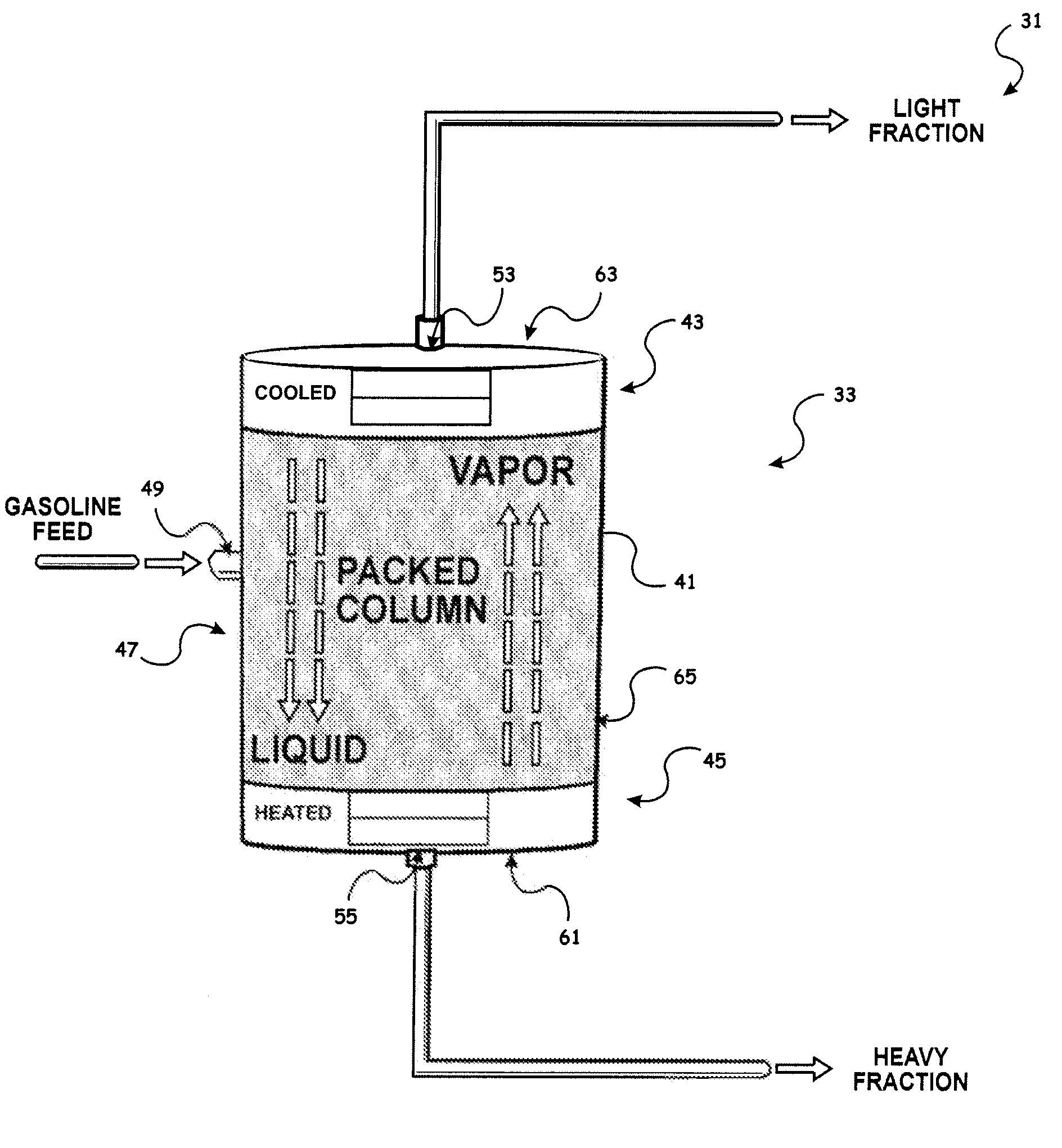
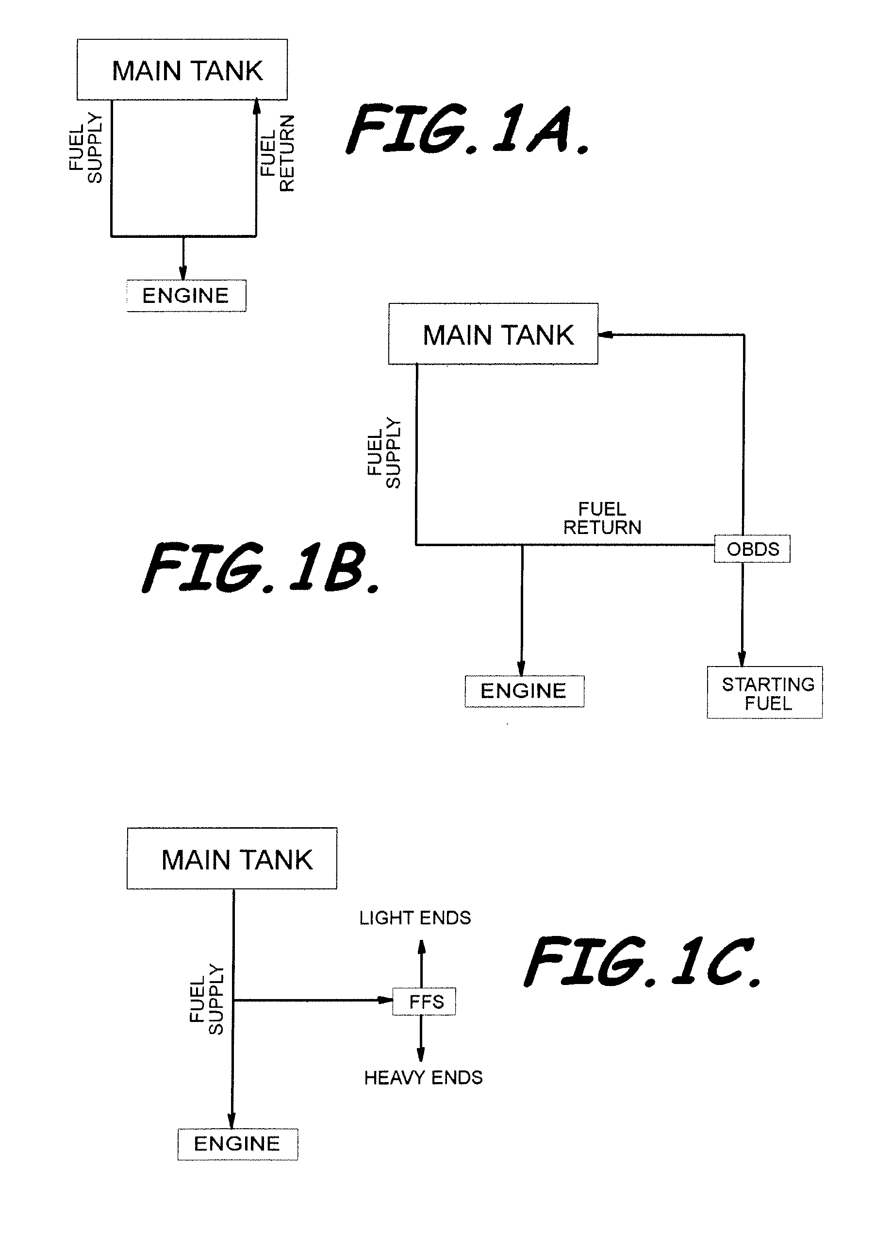
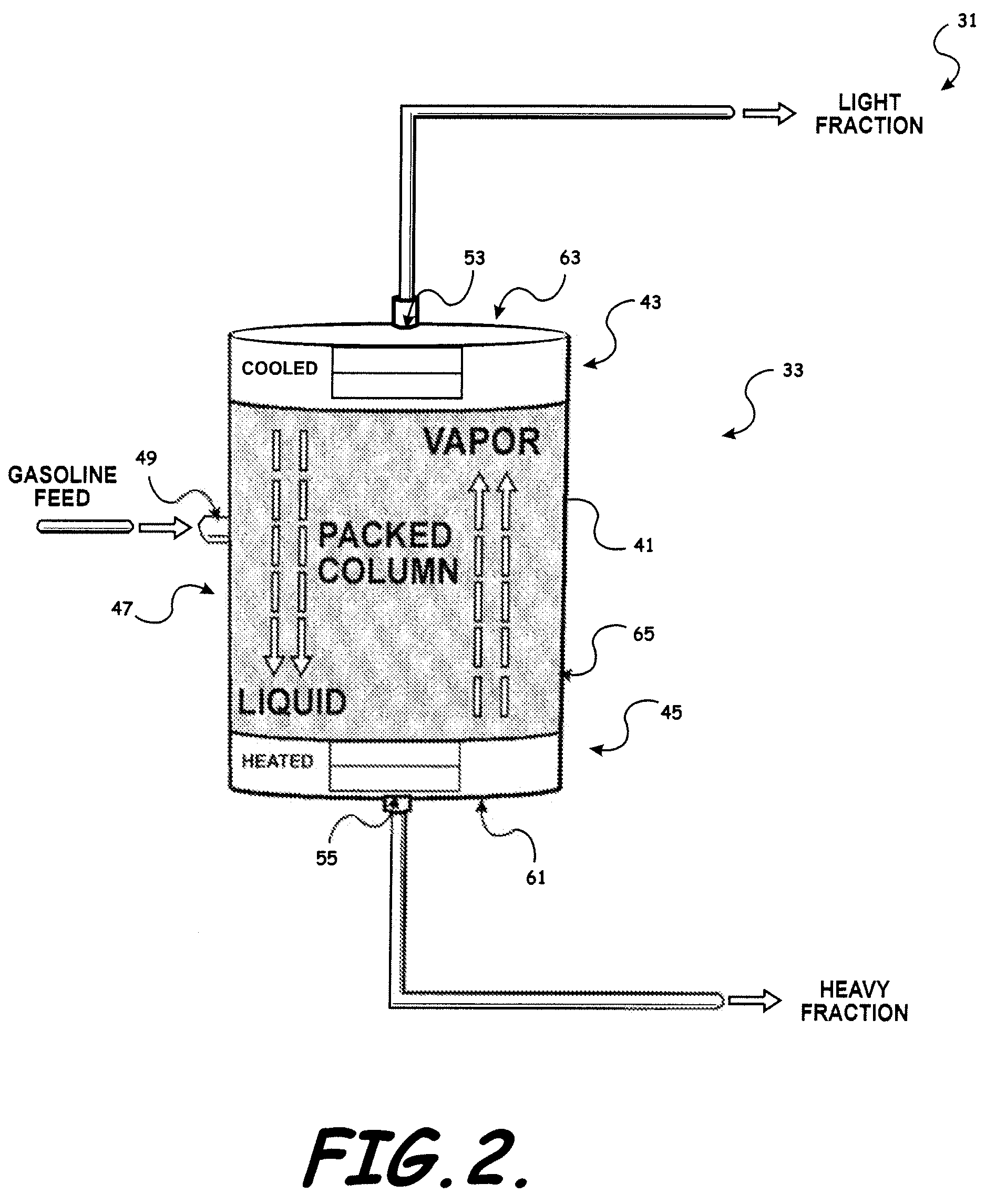
[0034]Provided is a Fuel Fractionation System (FFS), which is an evolution of the On-Board Distillation System (OBDS). The various embodiments of the FFS differ from the OBDS and other alternative fuel systems in a number of very significant ways. FIGS. 1A-11 assist in illustrating embodiments of the FFS and methods and in highlighting some of these differences, particularly as...


PUM

PropertyMeasurementUnit
boiling pointaaaaaaaaaa
temperatureaaaaaaaaaa
temperaturesaaaaaaaaaa

Abstract

A Fuel Fractionation System (FFS) and associated methods to generate and store a fuel for internal combustion engines is provided. FFS provides a distillation column assembly to distill liquid fuel to form a volatile light fraction secondary fuel. The distillation column assembly includes a vaporization module to vaporize a feed fuel in the distillation column and includes a condensation module to condense heavy fraction components of the vaporized feed fuel. FFS also provides a controller positioned to control the vaporization of feed fuel in the distillation column to thereby control the separation of the feed fuel into light fraction fuel and heavy fraction fuel components, and positioned to control the condensation of the heavy fraction components so that fuel exiting a light fraction output port in the distillation column is substantially light fraction fuel components by volume.

Description

RELATED APPLICATIONS[0001]This patent application claims the benefit of and priority to U.S. Provisional Application No. 60 / 774,683, filed on Feb. 17, 2006, incorporated by reference herein in its entirety.BACKGROUND OF THE INVENTION[0002]1. Field of the Invention[0003]The present invention relates to the engine industry, particularly engine fuel systems to fuel powered engines, and more specifically to a fuel system and method for reducing vehicle hydrocarbon emissions.[0004]2. Description of Related Art[0005]Since as early as 1942, particularly in urban areas having a high concentration of motor vehicles, air pollution from internal combustion engines has been recognized as an undesirable consequence of a mobile society. Emissions from the internal combustion engines arise from several sources and can vary considerably in both amount and composition depending on the engine type, operating point, condition, design, and fuel volatility. For engines without some form of emissions con...

Claims


Application Information

Patent Timeline
Patent Type & Authority Patents(United States)
IPC IPC(8): F02B51/00
CPCB01D3/28C10G7/02F02B51/00F02M33/00F02M25/08
Inventor ASHFORD, MARCUSMATTHEWS, RON
Owner BOARD OF RGT THE UNIV OF TEXAS SYST
Why Eureka
Try Eureka