Process for producing coke

a coke and coke technology, applied in the coke carbonaceous material field, can solve the problems of inconsistent coke quality, high volatile matter formation, inconsistent coke strength, porosity and particle size, etc., and achieve the effect of improving coke operation and/or coke quality

Inactive Publication Date: 2008-05-13
PHILLIPS 66 CO
View PDF29 Cites 11 Cited by
  • Summary
  • Abstract
  • Description
  • Claims
  • Application Information

AI Technical Summary

Benefits of technology

[0014]In yet a further aspect of the invention, a delayed coking process is provided which may be readily and advanta

Problems solved by technology

Each succeeding increment of feedstock, however, is coked for a lesser period of time and the final portion of feedstock introduced to the coking drum is subjected to coking conditions only for a relatively short period of time.
In view of this, problems can be encountered in obtaining coke product having consistent properties throughout the drum.
Unconverted feedstock in the coking drum at the end of the coking process can result in the formation of coke that is high in volatile matter.
However, coke having varying levels of volatile matter can be found throughout a coke drum, suggesting that coke strength, porosity and particle size, are not consistent throughout the drum.
Coke which is not consistent in properties throughout the drum presents problems in production of both electrodes for the steel industry and anodes for the aluminu

Method used


Image

  • Process for producing coke
  • Process for producing coke
  • Process for producing coke

Examples


example 4

[0083]A coking process was conducted utilizing the coking vessels and feedstock described in the previous Examples 1-3. For Example 4, a coking process according to preferred aspects of the invention was performed. The results were compared to those from Comparative Example 1.

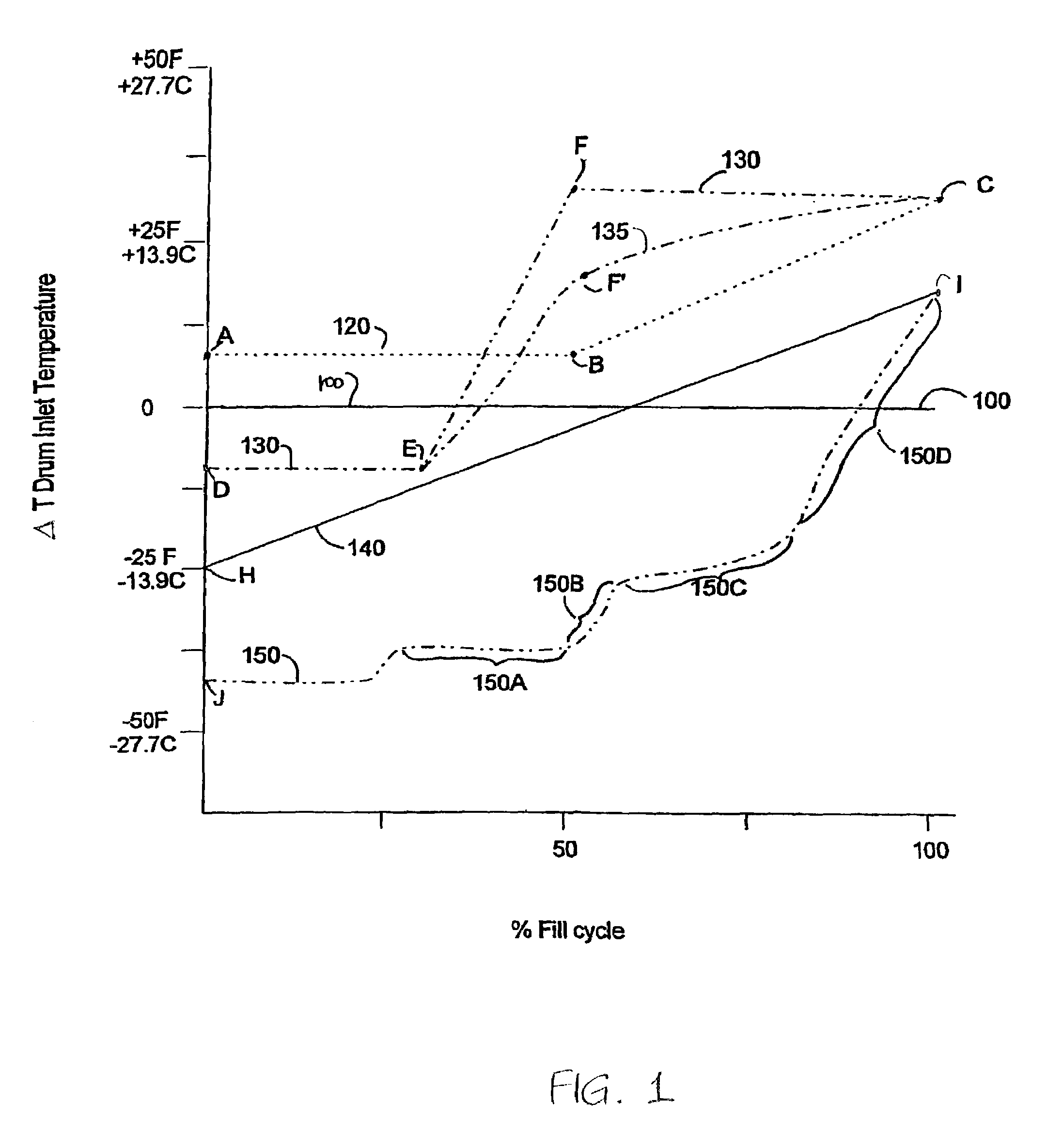
[0084]For Example 4, feedstock was supplied having drum inlet temperature controlled according to a substantially linear increasing temperature profile, and the operating pressure was maintained at 95 psig (655.0 kPa) during the fill cycle. The feedstock was provided at a constant volumetric fill rate for the duration of the fill cycle, which was the same for each of the processes. The temperature profiles used in each process are depicted in FIG. 13, where lines 300 and 380 correspond to Comparative Example 1, and Example 4, respectively.

[0085]As described above, Comparative Example 1 pertains to a conventional coking process where the operating pressure was maintained at 70 psig (482.6 kPa) throughout the fil...

example 5

[0091]A series of coke samples made from a commercial feedstock (Feedstock A) were produced in a small laboratory scale coke vessel. The vessel was a vertically oriented tubular reactor having an outside diameter of approximately 1½ inches, and a length of approximately 16 inches. This vessel was heated by placing it into a heater block having embedded electrical resistance elements. The coke samples were produced by reacting the thermal tar at a constant coking temperature of 875° F. (which corresponded to a typical coking temperature within a full scale coke drum). The pressure of the coking vessel was maintained at 100 psig during the coking reaction. Each of the samples was allowed to react for one of different time intervals, namely 2, 4, 8, 16, 32, and 64 hours.

[0092]At the end of the designated reaction period, the vessel was cooled and the contents were withdrawn. The quality of the coke produced was analyzed by determining the coefficient of thermal of expansion (CTE) using...

example 6

[0093]The same procedure as described in Example 5 was performed, except a different commercial feedstock, Feedstock B was used, and the coke vessel pressure was maintained at 60 psig. Each of the samples was allowed to react for one of different time intervals, namely 4, 8, 16, 32, 64 and 128 hours. FIG. 9 and Table 4 provide the data obtained from this example. As seen in FIG. 9, a significant decrease in the CTE was observed when the reaction time exceeded about 8 hours, and dramatically improved for longer durations of reaction time.

[0094]

TABLE 4Example 5 (100 psig,Example 6 (60 psig,Feedstock A)Feedstock B)Reaction Time, hrCTE (1 × 10⁻⁷)CTE (1 × 10⁻⁷)211.7 48.515.8 83.76.9162.42.1322.51.9642.31.9128—2.0

[0095]The batch operation performed in Examples 5 and 6 suggests that there can be a beneficial effect on the ultimate coke quality obtained in a commercial coking process due to an increased average reaction time available to the reactants in the coke drum. It appears that an in...


PUM


Abstract

A delayed coking process for producing more uniform and higher quality coke by increasing the drum inlet temperature of the feedstock at least 2° F. during a fill cycle.

Description

RELATED APPLICATIONS[0001]This application claims priority from U.S. Provisional Application Ser. No. 60 / 314,652, filed Aug. 24, 2001.TECHNICAL FIELD[0002]The present invention relates to a delayed coking process. More particularly, the invention relates to a delayed coking process for producing more uniform and higher quality coke.BACKGROUND OF THE INVENTION[0003]Coking processes have been practiced for many years and are an important source of revenue for many refineries. In a coking process, heavy hydrocarbon feedstock is thermally decomposed, or cracked, into coke and lighter hydrocarbon products. Of the various types of coking processes currently used in the petroleum refining industry, delayed coking has emerged as the technology of choice by most refiners due to its lower investment costs and its ability to produce comparable yields of products but of higher quality.[0004]A typical delayed coking process is a semi-continuous process in which heavy hydrocarbon feedstock is hea...

Claims


Application Information

Patent Timeline
IPC IPC(8): C10G9/14C10B57/04C10B55/00
CPCC10B55/00
Inventor NEWMAN, BRUCE A.MCCONKEY, IVAN G.GODDARD, BRUCE R.ROTH, JAMES R.
Owner PHILLIPS 66 CO
Why Eureka
Try Eureka