Solid-state thermal neutron detector

a solid-state thermal neutron and detector technology, applied in the direction of instruments, biochemistry apparatus and processes, measurement with semiconductor devices, etc., can solve the problems of difficult boron compound layer ohmic contact, electronic noise and arcing, and the bulky bulk of common-use thermal neutron detectors such as gas proportional counters and scintillation counters

Inactive Publication Date: 2008-05-13
NAVY SEC OF THE UNITED STATES +1
View PDF13 Cites 39 Cited by
  • Summary
  • Abstract
  • Description
  • Claims
  • Application Information

AI Technical Summary

Problems solved by technology

Commonly used thermal neutron detectors such as gas proportional counters and scintillation counters tend to be bulky and are not readily configured for covering large areas.
Gas proportional counters require high voltages, on the order of kilovolts, which can be electronically noisy and susceptible to arcing due to environmental conditions.
However, a significant problem with these solid-state neutron detectors is the difficulty of forming ohmic contacts to the boron compound layer, which is a semiconducting material.
However, forming multiple layers is expensive because each layer requires individual processing to create a structure that has good electrical conductance and adhesion between the multiple layers and the boron carbide layer.
Such a diode structure is operated with a reverse bias voltage applied, which can lead to an unacceptably high background, or dark, current.

Method used


Image

  • Solid-state thermal neutron detector
  • Solid-state thermal neutron detector
  • Solid-state thermal neutron detector

Examples


Embodiment Construction

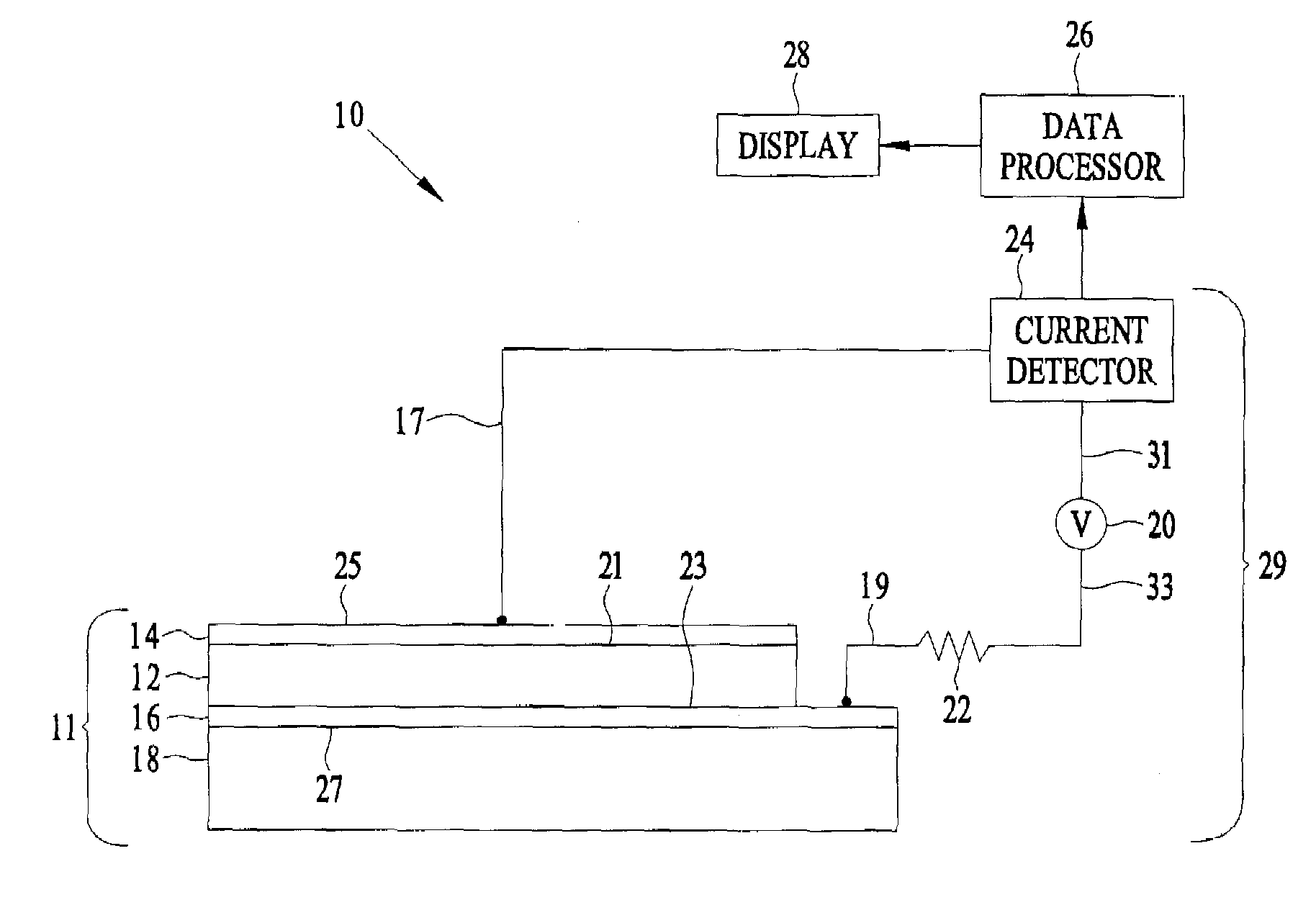
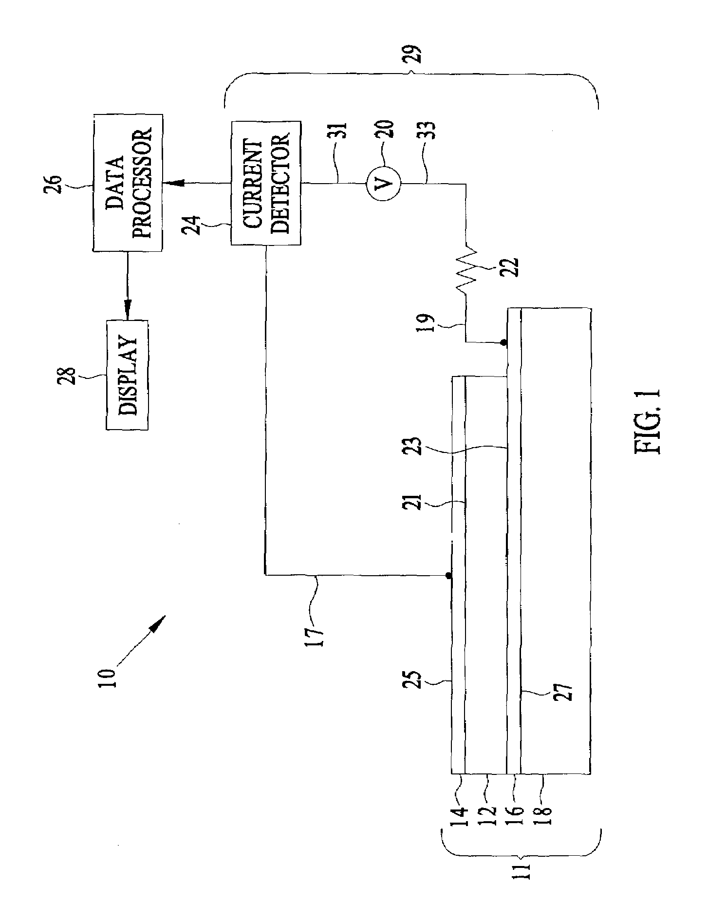
[0011]Referring to FIG. 1, there is shown an embodiment of a solid-state thermal neutron detector 10 that includes a layered structure 11 defined by an electrically insulating substrate 18, a first electrode 16 formed on the substrate, a neutron-reactive layer 12 affixed to the first electrode 16, and a second electrode 14 affixed to the neutron-reactive layer 12. A neutron-reactive layer is a layer in which free electron-hole pairs, or charge carriers, are created when thermal neutrons react with atoms in the layer. For example, in applications wherein neutron-reactive layer 12 consists essentially of a boron compound, the following primary reaction is believed to occur when neutrons are incident upon neutron-reactive layer 12: n+10B→7Li*+α, where n represents a neutron, B represents a boron atom, Li* represents an excited lithium atom, and α represents an alpha particle (helium nucleus). The alpha particles, with an energy of about 2.3 MeV, collide with other atoms in neutron-reac...


PUM

PropertyMeasurementUnit
thicknessaaaaaaaaaa
thicknessaaaaaaaaaa
temperaturesaaaaaaaaaa

Abstract

A solid-state thermal neutron detector comprises: a layered structure that includes; an electrically insulating substrate; a first electrode affixed to the substrate; a neutron-reactive layer affixed to and in ohmic contact with the first electrode; and a second electrode affixed to and in ohmic contact with the neutron-reactive layer; a voltage source electrically coupled to the first and second electrodes; and an electrical current detector electrically coupled in series between the layered structure and the voltage source.

Description

BACKGROUND OF THE INVENTION[0001]Commonly used thermal neutron detectors such as gas proportional counters and scintillation counters tend to be bulky and are not readily configured for covering large areas. Gas proportional counters require high voltages, on the order of kilovolts, which can be electronically noisy and susceptible to arcing due to environmental conditions. Solid-state neutron detectors based on silicon or germanium photodiodes and phototransistors exist, but they tend to have small detection apertures, and typically require a neutron converter foil, such as Gd, in front of the semiconductor device. One class of solid-state neutron-detectors detects electron-hole pairs that cross a semiconductor junction. The electron hole pairs are produced by reaction particles formed as a result of neutron reaction within films containing neutron-sensitive material incorporated within the detector. One such solid-state neutron detector includes a silicon semiconductor having a la...

Claims


Application Information

Patent Timeline
Patent Type & Authority Patents(United States)
IPC IPC(8): H01J40/00G01T3/08
CPCG01T3/08
Inventor LOSEE, JON R.HICKS, J. CHARLESJACOBS, EVERETT W.MCGINNIS, WAYNE C.BOSS, ROGER D.
Owner NAVY SEC OF THE UNITED STATES
Why Eureka
Try Eureka