Multi-layer spectral purity filter, lithographic apparatus including such a spectral purity filter, device manufacturing method, and device manufactured thereby

a spectral purity filter and multi-layer technology, applied in the field of lithographic equipment, can solve the problems of reducing difficult to produce gratings, harmful ultraviolet radiation, etc., and achieve the effect of improving the spectral purity of radiation beams

Active Publication Date: 2008-05-13
ASML NETHERLANDS BV
View PDF15 Cites 24 Cited by
  • Summary
  • Abstract
  • Description
  • Claims
  • Application Information

AI Technical Summary

Benefits of technology

[0009]It is an aspect of the present invention to provide a spectral purity filter which is capable of mitigating debris emitted from a radiation source and also improving the spectral purity of a radiation beam.
[0012]The spectral purity filter may suppress undesired radiation while transmitting desired radiation with low wavelengths, such as EUV radiation. The multi-layered structure may therefore be designed and adapted to reflect or absorb undesired radiation (e.g. deep ultraviolet (DUV) radiation) while transmitting desired radiation (e.g. EUV).
[0014]The spectral purity filter may filter out undesired radiation, such as DUV radiation. For example, on the transmission of radiation through the spectral purity filter, the ratio of EUV radiation to DUV radiation may be enhanced by about 100 times, 1000 times or even up to about 105 times. A significant improvement in the spectral purity of a radiation beam on transmission through a spectral purity filter according to the present invention may therefore be obtained.
[0018]The multi-layered structure of the spectral purity filter may be designed to be strong and robust so that the filter is not damaged by debris emitted from a radiation source.
[0019]The multi-layered structure of alternating layers may be deposited onto a mesh-like structure. The mesh-like structure may be in the form of a honeycomb structure and may penetrate from one side of the multi-layered structure to the other. The mesh-like structure may include a plurality of apertures within which material forming the multi-layered structure of alternating layers may be deposited. The mesh may be formed from any suitable electroformable material, for example Ni and Cu. The apertures in the mesh-like structure may have a size range of about 0.01-5 mm2, for example about 1-1.5 mm2. The mesh-like structure may improve the strength of the multi-layered structure in the spectral purity filter. The spectral purity filter may therefore be made of a thinner multi-layered structure in comparison to spectral purity filters without a mesh. This may improve the transmission of EUV radiation. A spectral purity filter including a mesh-like structure may therefore be substantially strengthened and may withstand greater pressure differences in comparison to filters with no mesh-like structure.
[0028]The spectral purity filters may also be easily removed from a lithographic apparatus, and then cleaned externally and repositioned in the lithographic apparatus, or substituted with a replacement spectral purity filter. By easy replacement of the spectral purity filter, this overcomes the need to disassemble a substantial part of a lithographic apparatus. The spectral purity filter of the present invention therefore has cost benefits in comparison to spectral purity filters existing in the prior art.

Problems solved by technology

This non-EUV radiation is harmful for an EUV lithography system, so it has to be removed by, for example, a spectral purity filter.
However, these gratings are difficult to produce, since the surface quality of a triangular shaped pattern on the spectral purity filters has to be very high.
However, commonly used debris mitigation methods, which include foil traps and gas buffers, do not guarantee effective debris protection.
Moreover, use of standard (e.g. Zr) thin filters transmissive for EUV is virtually impossible due to the fragility of the filters and low heat-load threshold.
However, having to accommodate such off-line cleaning makes vacuum and mechanical design of a lithographic apparatus extremely complicated.
Off-line cleaning also involves a significant amount of down time for the lithographic apparatus.
A further problem of existing spectral purity filters is that they change the direction of a radiation beam from an EUV source.
The added mirror introduces unwanted losses into the system.

Method used


Image

  • Multi-layer spectral purity filter, lithographic apparatus including such a spectral purity filter, device manufacturing method, and device manufactured thereby
  • Multi-layer spectral purity filter, lithographic apparatus including such a spectral purity filter, device manufacturing method, and device manufactured thereby
  • Multi-layer spectral purity filter, lithographic apparatus including such a spectral purity filter, device manufacturing method, and device manufactured thereby

Examples


Embodiment Construction

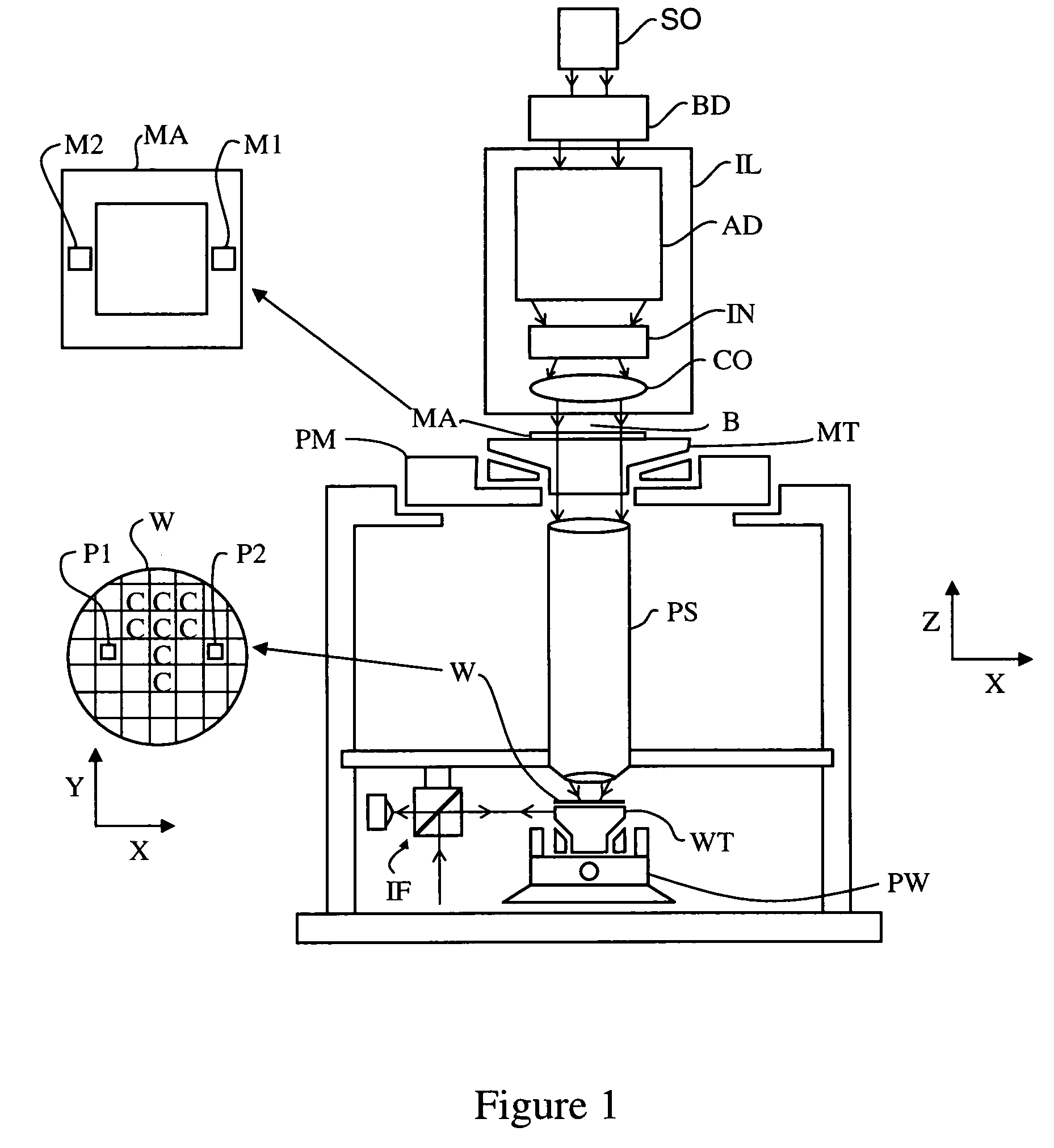
[0047]FIG. 1 schematically depicts a lithographic apparatus including an illumination system (illuminator) IL configured to condition a radiation beam B (e.g. UV radiation or EUV radiation). A support (e.g. a mask table) MT is configured to support a patterning device (e.g. a mask) MA and is connected to a first positioning device PM configured to accurately position the patterning device in accordance with certain parameters. A substrate table (e.g. a wafer table) WT is configured to hold a substrate (e.g. a resist-coated wafer) W and is connected to a second positioning device PW configured to accurately position the substrate in accordance with certain parameters. A projection system (e.g. a refractive projection lens system) PS is configured to project a pattern radiation beam B onto a target portion C (e.g. including one or more dies) of the substrate W.

[0048]The illumination system may include various types of optical components, such as refractive, reflective, magnetic, elect...


PUM


Abstract

A multi-layered spectral purity filter improves the spectral purity of extreme ultra-violet (EUV) radiation and also collects debris emitted from a radiation source.

Description

BACKGROUND OF THE INVENTION[0001]1. Field of the Invention[0002]The present invention relates to a lithographic apparatus and a method of using the apparatus in the manufacture of a device such as an integrated circuit (IC). In particular, the present invention relates to multi-layered spectral purity filters which improve the spectral purity of an Extreme Ultra-Violet (EUV) radiation beam and also filter debris emitted from a radiation source.[0003]2. Description of the Related Art[0004]A lithographic apparatus is a machine that applies a desired pattern onto a substrate, usually onto a target portion of the substrate. A lithographic apparatus can be used, for example, in the manufacture of integrated circuits (ICs). In that instance, a patterning device, which is alternatively referred to as a mask or a reticle, may be used to generate a circuit pattern to be formed on an individual layer of the IC. This pattern can be transferred onto a target portion (e.g. including part of, one...

Claims


Application Information

Patent Timeline
Patent Type & Authority Patents(United States)
IPC IPC(8): G02B5/20
CPCG03F7/70191G03F7/70308G03F7/70575G03F7/70916G03F7/70941G03F7/70291
Inventor BANINE, VADIM YEVGENYEVICHMOORS, JOHANNES HUBERTUS JOSEPHINASHMAENOK, LEONIDSALASHCHENKO, NIKOLAY
Owner ASML NETHERLANDS BV
Why Eureka
Try Eureka