Supercharge Your Innovation With Domain-Expert AI Agents!

Earphone antenna and portable radio equipment provided with earphone antenna

a portable radio and antenna technology, applied in the field of earphone antennas, can solve the problems of deteriorating antenna performance, affecting the stability of reception, and unable to obtain sufficient reception sensitivity, so as to reduce the influence of the human body, wide band range, and high gain

Inactive Publication Date: 2008-05-13
SONY CORP
View PDF30 Cites 21 Cited by
  • Summary
  • Abstract
  • Description
  • Claims
  • Application Information

AI Technical Summary

Benefits of technology

The present invention provides an earphone antenna and a portable radio apparatus with the earphone antenna that can reduce the impact of the human body and achieve a high gain in a wide band range. The earphone antenna includes a first earphone cable with insulation-coated signal lines, a shielded cable with a coaxial cable and a second signal line, and a connection block that connects the shielded cable to the portable radio apparatus. The earphone antenna has a high impedance in the frequency range of audio signals and low impedance in the frequency range of high-frequency signals, while the connection block has a low impedance in the frequency range of audio signals and high impedance in the frequency range of high-frequency signals. The earphone antenna includes a second earphone cable with insulation-coated signal lines and a high frequency choke. The portable radio apparatus with the earphone antenna has improved stability and portability.

Problems solved by technology

In the portable radio equipment which uses a rod antenna and / or an earphone antenna, when put on a human body for use, there has been a problem that because of a significant deterioration of antenna performance when put on the human body, such as in television broadcasts where signals with a large amount of information, e.g., video signals, are processed, a sufficient reception sensitivity cannot be obtained.
In particular, the earphone antenna which utilizes the signal wire for transmitting audio signals to the earphones as an antenna has had a problem that because the earphone and / or the signal wire make direct contact with the human body, the human body has caused a significant influence on the radio equipment via the antenna to substantially deteriorate the stability of reception.
Accordingly, with a conventional rod antenna or earphone antenna, the performance of which is inferior to a fixed-type antenna, it has been extremely difficult to secure a sufficient sensitivity in the required frequency band range.
Still further, because the rod antenna and the earphone antenna are monopole antennas which resonate at λ / 4, their reception sensitivity is greatly influenced by the ground size of the portable radio terminal, thereby limiting the design of the portable radio equipment.

Method used


Image

  • Earphone antenna and portable radio equipment provided with earphone antenna
  • Earphone antenna and portable radio equipment provided with earphone antenna
  • Earphone antenna and portable radio equipment provided with earphone antenna

Examples


Embodiment Construction

[0027]A preferred exemplary embodiment of the present invention will be described in detail by referring to the accompanying drawings in the following. However, it should be understood that the present invention is not limited thereto, and many changes and modifications thereof can be contemplated within the scope of the present invention.

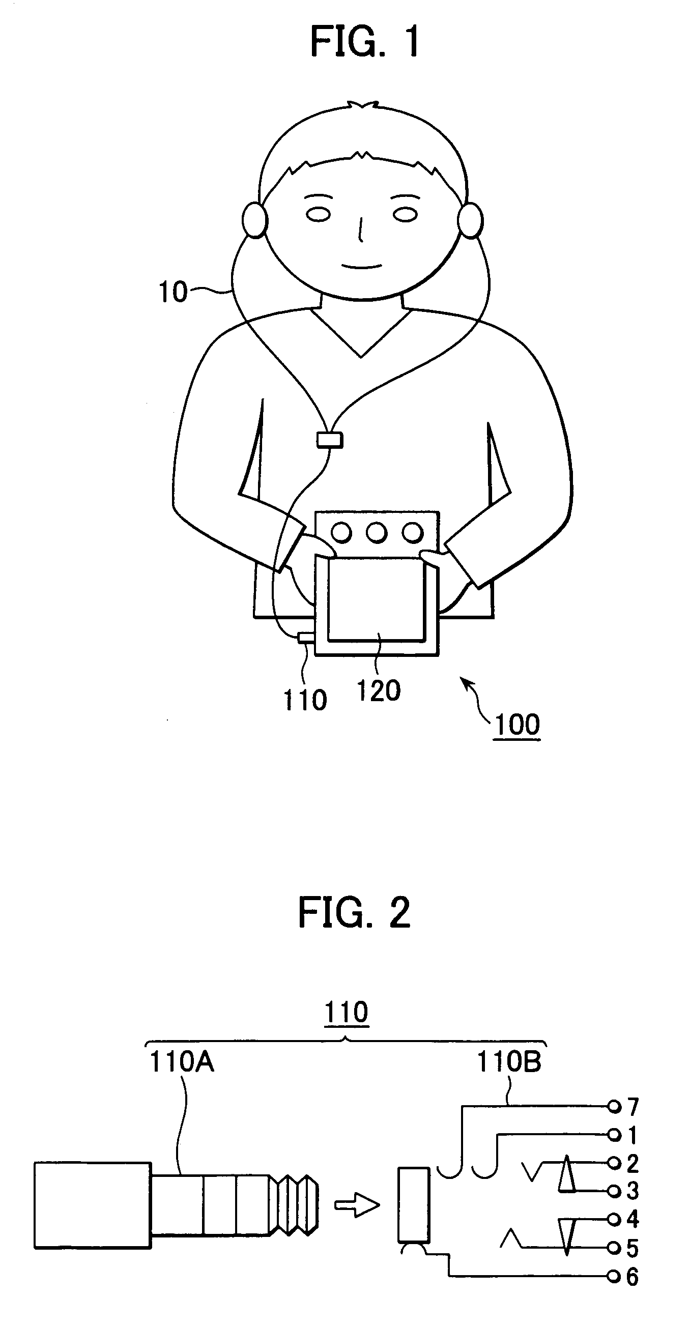
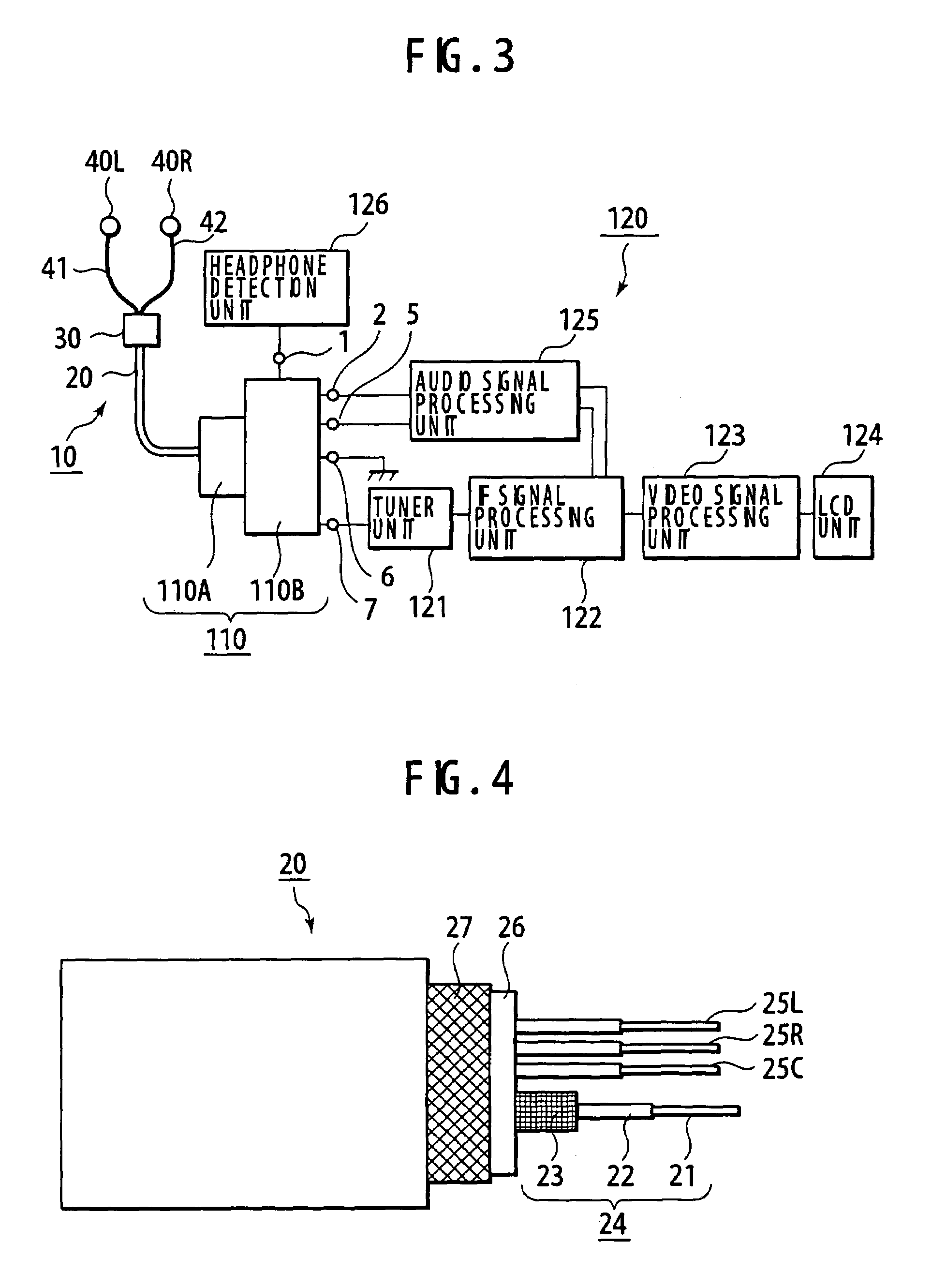
[0028]The present invention is applicable to, for example, an LCD television receiver 100 shown in FIG. 1. In this liquid crystal display television receiver 100, an earphone antenna 10 according to an embodiment of the present invention is connected to the main body of the receiver 120 via a pin jack connector 110.

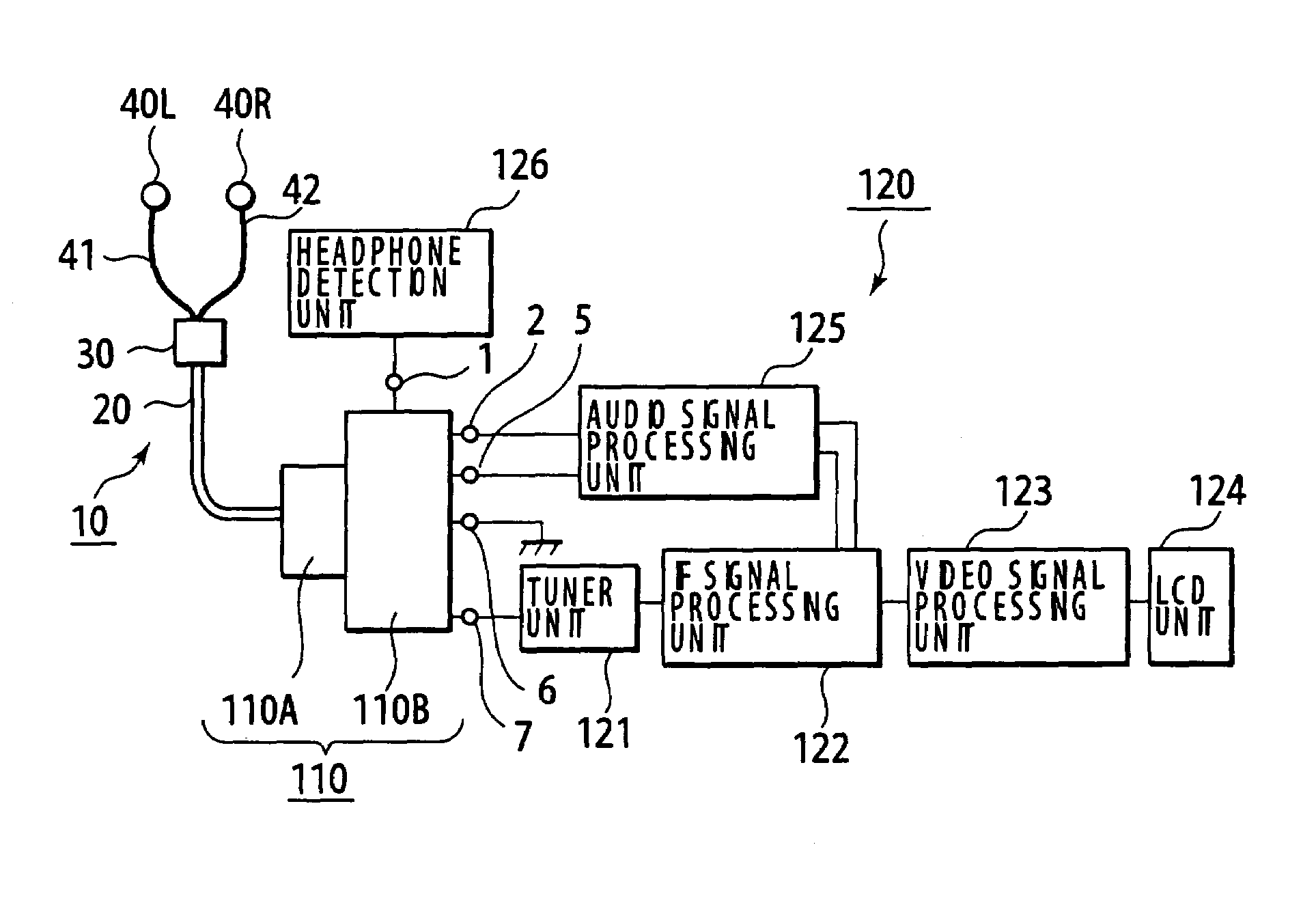
[0029]The pin jack connector 110, as shown in FIG. 2, is composed of a five-electrode pin 110A and a jack 110B to which five kinds of lines, i.e., antenna 7, headphone detection 1, audio L channel 2, audio R channel 5, and ground 6 are connected, respectively.

[0030]In the main body of the receiver 120, as shown in FIG. 3, there are provi...


PUM


Abstract

An earphone antenna includes an audio signal transmission path formed by connecting a first shield wire of a coaxial cable to a ground, connecting a central conductor of the coaxial cable to a pair of first signal lines of an earphone cable via a capacitor which exhibits high impedance in a frequency range of audio signals and low impedance in a frequency range of high frequency signals, and connecting a second signal line and a grounding wire, respectively, to the pair of first signal lines via a high frequency choke which exhibits low impedance in the frequency range of audio signals and high impedance in the frequency range of high frequency signals. Connecting the second shield wire to the ground causes formation of a sleeve antenna by the earphone cable and the second shield wire.

Description

CROSS-REFERENCE TO RELATED APPLICATIONS[0001]The present application claims priority from Japanese Patent Application No. JP2004-167551 filed on Jun. 4, 2004, the disclosure of which is hereby incorporated by reference herein.BACKGROUND OF THE INVENTION[0002]The present invention relates to an earphone antenna for portable radio equipment which is put on a human body during use, and to portable radio equipment provided with this earphone antenna.[0003]Conventionally, in portable radio equipment to be carried on a human body during use, such as a pager, a radio receiver, an LCD television receiver and the like, a rod antenna or an earphone antenna which utilizes a signal wire for transmitting audio signals to earphones is used as an antenna. For example, such an earphone antenna is disclosed in Japanese Patent Application Publication No. 2003-163529.[0004]In the portable radio equipment which uses a rod antenna and / or an earphone antenna, when put on a human body for use, there has b...

Claims


Application Information

Patent Timeline
Patent Type & Authority Patents(United States)
IPC IPC(8): H04M1/00H01Q1/24H01Q1/46H01Q9/16H01Q9/18H04B1/18H04R1/10
CPCH01Q1/46H01Q9/16H01Q1/273H04B1/38H04R1/10
Inventor YOSHINO, YOSHITAKA
Owner SONY CORP
Features
  • R&D
  • Intellectual Property
  • Life Sciences
  • Materials
  • Tech Scout
  • Unparalleled Data Quality
  • Higher Quality Content
  • 60% Fewer Hallucinations
Learn More