
Droplet ejecting device, droplet ejecting method, and electronic optical device

a technology of droplet ejection and droplet ejection, which is applied in the direction of coating, printing, instruments, etc., can solve the problems of difficulty in forming a droplet of a sufficiently small volume, difficulty in high-precision patterning, and neither approach provides a satisfactory

Inactive Publication Date: 2008-05-20
SEIKO EPSON CORP
View PDF11 Cites 9 Cited by
  • Summary
  • Abstract
  • Description
  • Claims
  • Application Information

AI Technical Summary

Benefits of technology

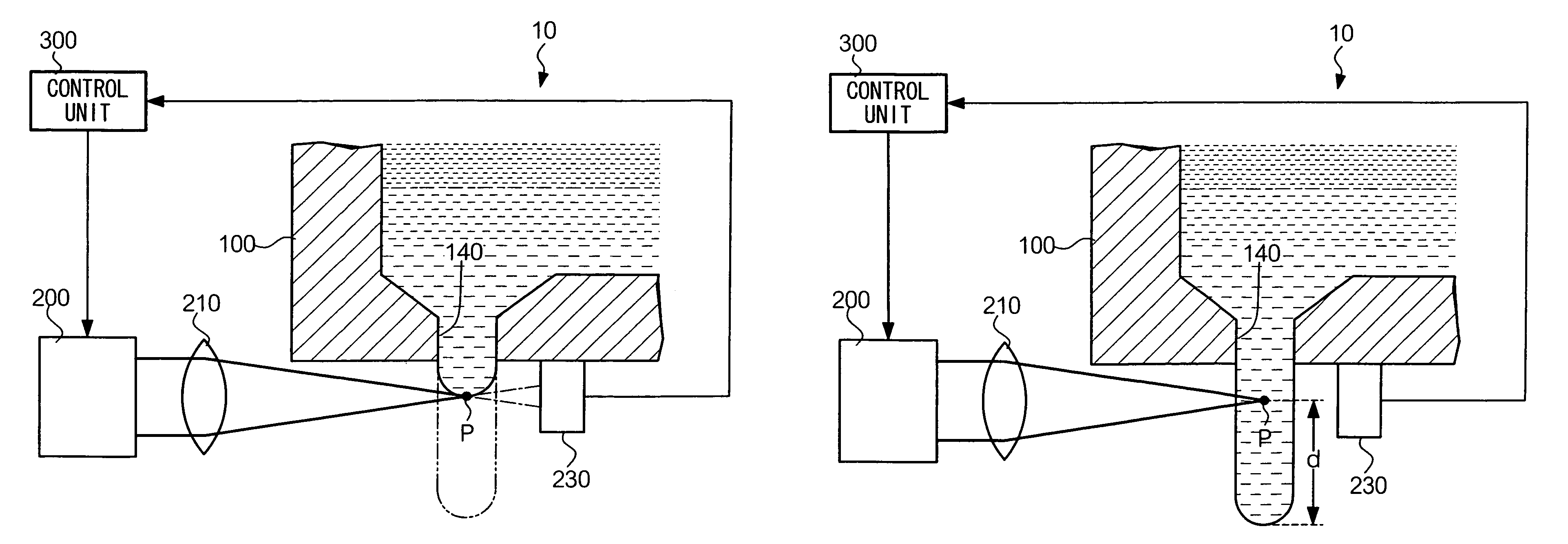
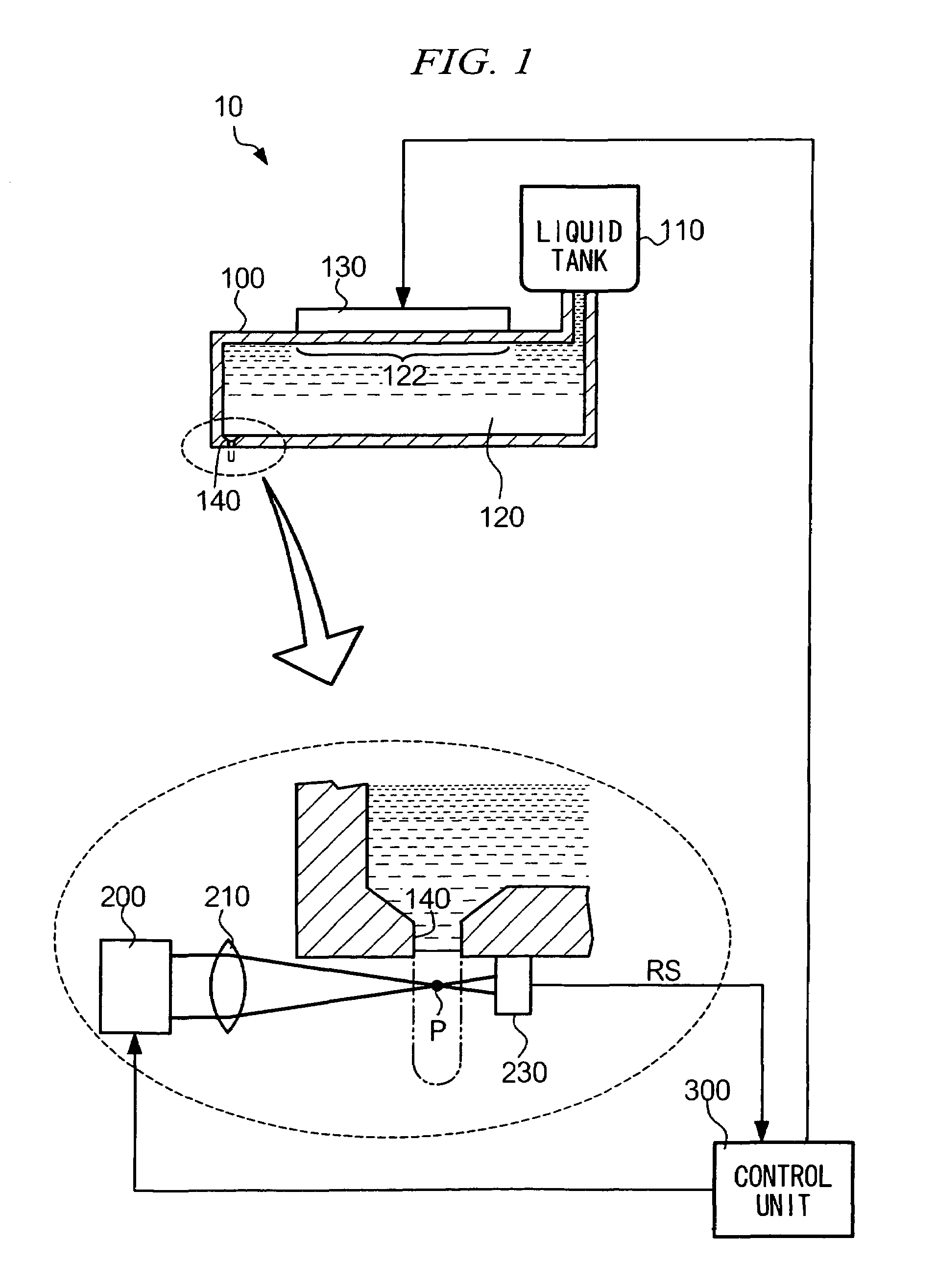
The present invention provides a droplet ejecting method and device that can reliably eject microscopic droplets from a high viscosity liquid. The method involves using a droplet formation assisting means to give energy to the liquid as it is ejected from an ejecting nozzle. This energy can be optical energy, such as coherent-light energy or thermal energy. The method can be used in various applications such as patterning wiring, color filters, photoresist, and to pattern elements in electronic optical devices. The invention also provides an electronic optical device comprising an element patterned using the droplet ejecting method.

Problems solved by technology

However, the higher the viscosity of a liquid from which droplets are ejected from a droplet ejecting device, the more difficult it is to form a droplet of a sufficiently small volume (i.e., to micronize a droplet), which makes it difficult to carry out high-precision patterning.
However, neither approach provides a satisfactory result.
If the ejection speed of the liquid column is increased, spattering tends to result; also the ejected liquid droplets tend to shift from their intended trajectory and hit the substrate inaccurately.
Thus, to date, a droplet ejecting device that is capable of micronizing droplets from a high viscosity liquid has not been available.

Method used


Image

  • Droplet ejecting device, droplet ejecting method, and electronic optical device
  • Droplet ejecting device, droplet ejecting method, and electronic optical device
  • Droplet ejecting device, droplet ejecting method, and electronic optical device

Examples


Embodiment Construction

[0049]Hereinafter, an embodiment of the present invention will be described with reference to the attached drawings.

[0050]FIG. 1 shows a peripheral configuration of an ejecting head of a droplet ejecting device according to an embodiment of the present invention. In the figure, a liquid tank 110 stores a liquid containing functional materials, and which is to be ejected from an ejecting head 100. Specifically, liquid tank 110 stores a liquid having a viscosity of about 20 mPa·s, and comprising microscopic particles of silver mixed into an organic solvent such as C14H30 (n-tetradecane). The liquid is used for the wiring patterning and is ejected from droplet ejecting device 10 as a droplet having a volume of 2 pl. It is to be noted, as is described later in various applications of droplet ejecting device 10, that the liquid ejected from the device 10 is not limited to a liquid used for wiring patterning, but may include any of: a liquid containing EL materials; an ink used for manufa...


PUM

PropertyMeasurementUnit
volumeaaaaaaaaaa
volumeaaaaaaaaaa
viscosityaaaaaaaaaa

Abstract

A droplet ejecting device includes an ejector that is adapted to eject a liquid stored in a pressure chamber from an ejecting nozzle, by applying pressure to the pressure chamber; an ejection timing detector that is adapted to detect a start timing at which a liquid column starts being ejected from the ejecting nozzle; a droplet separator that is adapted to give, to the liquid column, an energy that separates the liquid column from the liquid stored in the pressure chamber; and a controller that is adapted to control the droplet separator to give an energy at a timing when a predetermined time period has elapsed since the start timing detected by the ejection timing detector.

Description

TECHNICAL FIELD[0001]The present invention relates to a droplet ejecting device and a droplet ejecting method for ejecting a droplet, and to an electronic optical device manufactured using the method.BACKGROUND ART[0002]A well-known patterning method employs a droplet ejecting device for forming a wiring pattern on a substrate. The droplet ejecting device generally drops onto a substrate liquid containing a functional material such as silver particles, thereby fixing the functional material on the substrate to form a wiring pattern. Such a patterning method is described, for example, in Japanese Patent Application Laid-Open Publication No. 2002-164635. The method enables cost effective wiring patterning requiring only a simple mechanical configuration as compared to a vapor deposition method using a shadow mask.[0003]FIGS. 12A to 12C are cross-sectional views of a major part of a conventional droplet ejecting device. The respective views illustrate a process of droplet formation and...

Claims

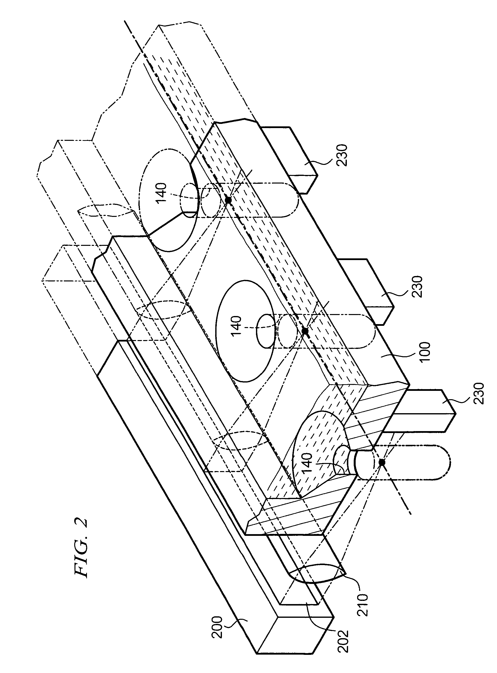

Application Information

Patent Timeline
Patent Type & Authority Patents(United States)
IPC IPC(8): B41J2/14B41J29/393B05C5/00B05C9/12G02F1/1335B05D3/06B05D7/00H01L51/50H05B33/10H05K3/00
CPCB41J2/14233B41J2/14104H05K3/00
Inventor MIURA, HIROTSUNA
Owner SEIKO EPSON CORP
Learn More