Hydroelectric device

a technology of hydroelectric devices and hydroelectric generators, which is applied in the direction of electric generator control, machines/engines, mechanical equipment, etc., can solve the problems of large hydroelectric facilities that may also have undesirable environmental impacts, system failures,

Active Publication Date: 2008-05-20
PECKHAM NICHOLAS
View PDF14 Cites 21 Cited by
  • Summary
  • Abstract
  • Description
  • Claims
  • Application Information

AI Technical Summary

Benefits of technology

[0014]In another aspect of the present invention, a self-cleaning filter is associated with the device to prevent debris from entering therein.

Problems solved by technology

Despite the advantages of hydroelectric power, the hydroelectric facilities in existence today suffer from a number of drawbacks.
Thus, such systems are not well-suited to use in areas having a substantially flat geography.
Large hydroelectric facilities may also have undesirable environmental impacts.
Engineers have attempted to address this issue by installing ‘fish ladders’ at many dams, but the results have shown only a limited success.
Because the water exiting the turbine generally contains little suspended sediment, the water tends to scour downstream riverbeds and erode riverbanks.
Further, the change in flow rate over the daily cycle of a hydroelectric dam can lead to erosion of sandbars and other downstream structures.
Dissolved oxygen content in the water released from the dam may be lower than normal, which can impact downstream flora and fauna, and temperature differences between the water held in the reservoir and the downstream water flow can also have a negative impact on biological populations downstream.
In addition to affecting plant and animal populations, hydroelectric dams may also adversely affect human populations in the area.
Such projects may require the relocation of persons living in the area where the reservoirs are planned.
In many places around the world, this can result in the loss of important cultural or ancestral lands.
Further, in some such projects historically important sites have been lost.

Method used


Image

  • Hydroelectric device
  • Hydroelectric device
  • Hydroelectric device

Examples


Embodiment Construction

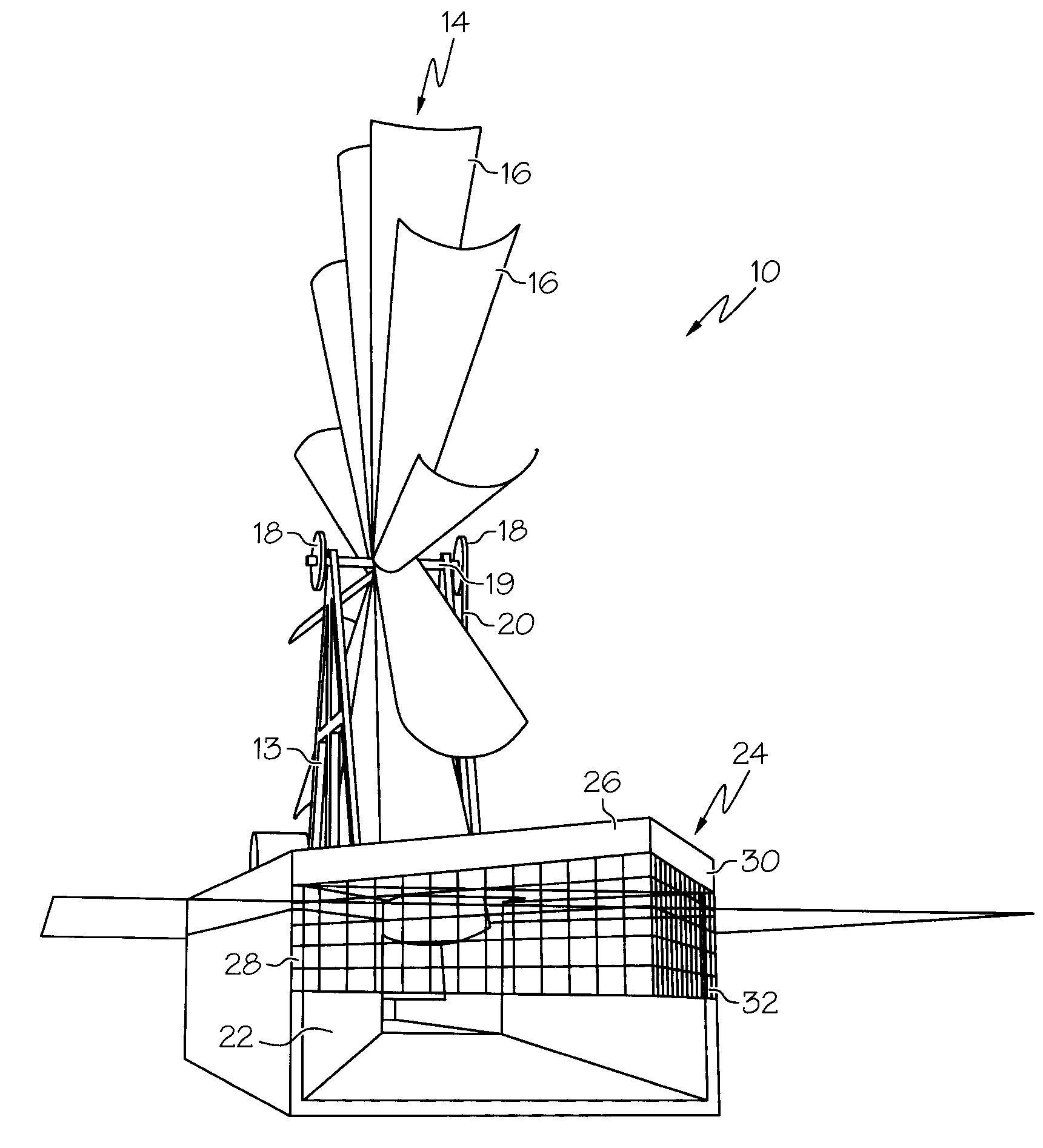
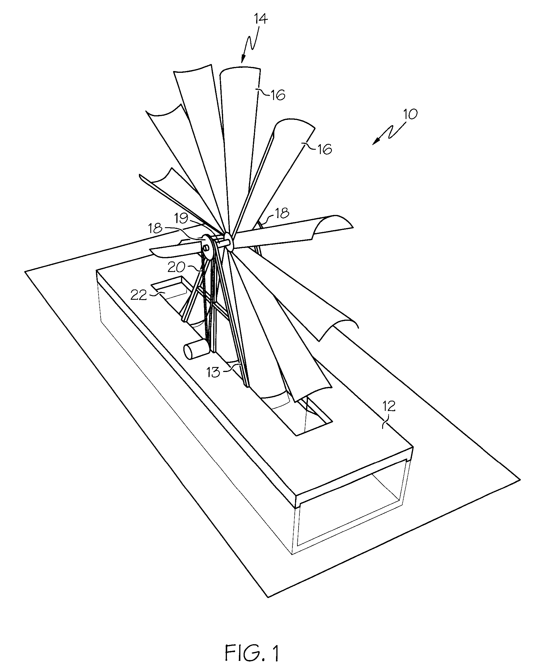
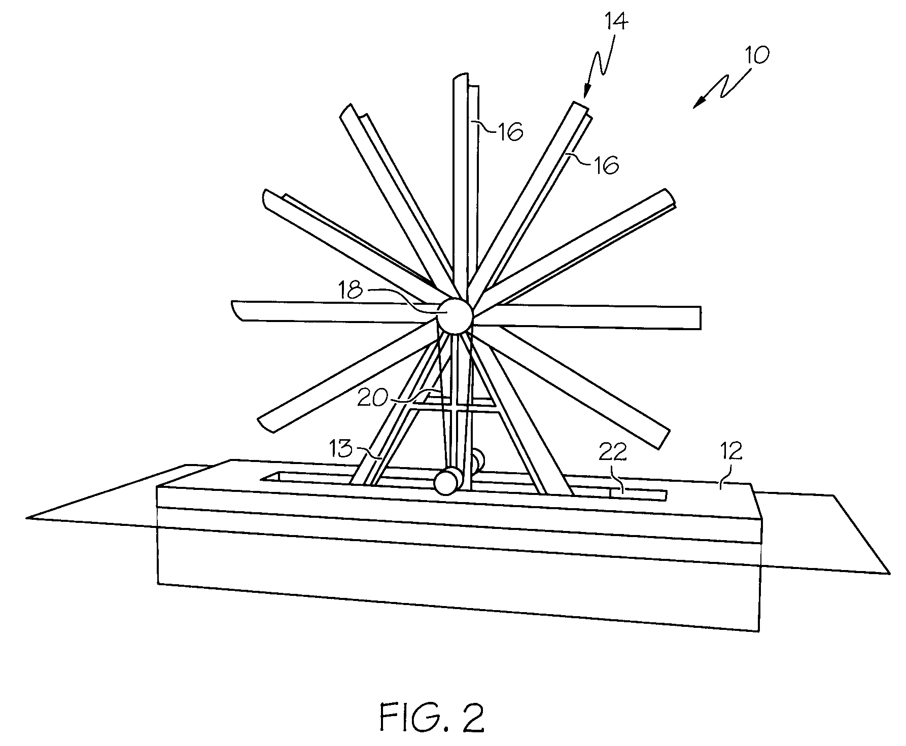
[0023]Turning now to the drawings, wherein like numerals indicate like parts, the numeral 10 indicates generally a hydroelectric device constructed in accordance with the teachings of the present invention. The present hydroelectric device preferably includes a base portion 12, a wheel 14, the wheel having a plurality of blades 16 disposed along a circumference thereof, a pulley 18 associated with said wheel, a belt 20 associated with said pulley, and a nozzle portion 22 associated with or formed within base portion 12. While these features are included in preferred embodiments of the present invention, it is contemplated that additions or modifications to these features may be provided as described below.

[0024]FIG. 1 is a side perspective view of one embodiment of the device of the present invention. As is shown, base portion 12 of device 10 is positioned in a river or other waterway during operative use of the device. Base portion 12 is positioned such that substantially all of ba...


PUM


Abstract

The present invention provides a hydroelectric device including generally a base portion with a top surface, a bottom surface, and opposing sidewalls defining an interior space of the base portion. The interior space of the base portion is such that it is wider near the ends of the base portion and narrower in the interior of the base portion, essentially forming a venturi. The base portion also includes a central slot along a longitudinal axis thereof. The present invention further includes a wheel support portion fixedly attached to the base portion, a wheel portion rotatably attached to the wheel support portion and having a plurality of blades extending from a center thereof, and an electrical generator operably engaged with the wheel portion.

Description

CROSS-REFERENCE TO RELATED APPLICATIONS[0001]Not Applicable.STATEMENT REGARDING FEDERALLY SPONSORED RESEARCH OR DEVELOPMENT[0002]Not Applicable.INCORPORATION BY REFERENCE OF MATERIAL SUBMITTED ON A COMPACT DISC[0003]Not Applicable.BACKGROUND OF THE INVENTION[0004]Mankind has made use of the power of water for thousands of years. The ancient Greeks used waterwheels to grind wheat into flour more than two-thousand years ago, and waterwheel technology spread across Europe during the height of the Roman empire. Over the subsequent millennia, hydropower technology spread to a variety of applications, including the production of electricity.[0005]Hydroelectric power is generally known in the art, and hydropower is a common means of producing electricity around the world. In some South American countries, hydroelectric power accounts for more than 50% of the national supply of electricity. Most hydroelectric power is generated from the potential energy stored in water when that water is da...

Claims


Application Information

Patent Timeline
Patent Type & Authority Patents(United States)
IPC IPC(8): F03B13/00
CPCF03B17/063H02K7/1823F05B2220/70644F05B2240/133Y02E10/28Y02E10/20
Inventor PECKHAM, NICHOLAS
Owner PECKHAM NICHOLAS
Why Eureka
Try Eureka